Temperature compensation for measurements, Temperature compensation for the rtc – Maxim Integrated 71M6513H Power Meter IC Family Software User Manual
Page 81
71M651x Software User’s Guide
5.11.3.Temperature Compensation for Measurements
Internal Compensation: The internal voltage reference of the 651X ICs is calibrated during device manufacture. Trim
data is stored in on-chip fuses.
For the 71M651X, the temperature coefficients TC1 and TC2 are given as constants that represent typical component
behavior.
For the 71M651XH, the temperature characteristics of the chip are measured during production and then stored in the
fuse registers TRIMBGA, TRIMBGB and TRIMM[2:0]. TC1 and TC2 can be derived from the fuses by using the rela-
tions given in the Electrical Specifications section. TC1 and TC2 can be further processed to generate the coefficients
PPMC and PPMC2.
TRIMM[2:0], TRIMBGA and TRIMBGB are read by first writing either 4, 5 or 6 to TRIMSEL (0x20FD) and then reading
the value of TRIM (0x20FF).
When the EXT_TEMP register in CE DRAM (address 0x38) is set to 0, the CE automatically compensates for tem-
perature errors by controlling the GAIN_ADJ register (CE DRAM address 0x2E) based on the PPMC, PPMC2, and
TEMP_X register values. In the case of internal compensation, GAIN_ADJ is an output of the CE.
External Compensation: Rather than internally compensating for the temperature variation, the bandgap tempera-
ture is provided to the embedded MPU, which then may digitally compensate the power outputs. This permits a sys-
tem-wide temperature correction over the entire system rather than local to the chip. The incorporated thermal coeffi-
cients may include the current sensors, the voltage sensors, and other influences. Since the band gap is chopper sta-
bilized via the CHOP_EN bits, the most significant long-term drift mechanism in the voltage reference is removed.
When the EXT_TEMP register in CE DRAM is set to 15, the CE ignores the PPMC, PPMC2, and TEMP_X register
values and applies the gain supplied by the MPU in GAIN_ADJ. External compensation enables the MPU to control
the CE gain based on any variable, and when EXT_TEMP = 15, GAIN_ADJ is an input to the CE.
5.11.4.Temperature Compensation for the RTC
The flexibility provided by the MPU allows for compensation of the RTC using the substrate temperature. To achieve
this, the crystal has to be characterized over temperature and the three coefficients Y_CAL, Y_CALC, and Y_CAL_C2
have to be calculated. Provided the IC substrate temperatures tracks the crystal temperature the coefficients can be
used in the MPU firmware to trigger occasional corrections of the RTC seconds count, using the RTC_DEC_SEC or
RTC_INC_SEC registers in I/O RAM.
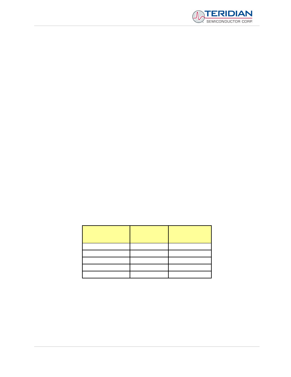
Example: Let us assume a crystal characterized by the measurements shown in Table 5-12:
Deviation from
Nominal
Temperature [°C]
Measured
Frequency [Hz]
Deviation from
Nominal
Frequency [PPM]
+50
32767.98
-0.61
+25
32768.28
8.545
0
32768.38
11.597
-25
32768.08
2.441
-50
32767.58
-12.817
Table 5-12: Frequency over Temperature
The values show that even at nominal temperature (the temperature at which the chip was calibrated for energy), the
deviation from the ideal crystal frequency is 11.6 PPM, resulting in about one second inaccuracy per day, i.e. more
than some standards allow. As Figure 5-24 shows, even a constant compensation would not bring much
improvement, since the temperature characteristics of the crystal are a mix of constant, linear, and quadratic effects.
Revision 2.4
TERIDIAN Proprietary
81 of 137
© Copyright 2005-2006 TERIDIAN Semiconductor Corporation