Ce image files, Common mpu addresses, Ce image files 5.10. common mpu addresses – Maxim Integrated 71M6513H Power Meter IC Family Software User Manual
Page 70: Var w
71M651x Software User’s Guide
5.9.CE IMAGE FILES
The CE code uses pre-designed, pre-validated algorithms and calculations that are accurate to the noise floor of the
integrated circuit, saving substantial engineering and development time.
The source code for the CE is proprietary. Only the code and data images (binary images) are available to the user.
The code image must be merged with the MPU code residing in flash memory. Before enabling the CE program, the
MPU has to upload the code and data images to the CE PRAM and DRAM, as described in the 71M6511 and
71M6513 Data Sheets.
Images of the CE data and program code are provided with the Demo Kits. They are to be linked into the object code.
CE images are provided by the following files:
1.
CE11C_CE.C:
This file provides the image of the 6511 CE program in C notation.
2.
CE11C_DAT.C:
This file provides the image of the 6511 CE default data in C notation.
3.
CE13B_CE.C:
This file provides the image of the 6513 CE program in C notation.
4.
CE13B_DAT.C:
This file provides the image of the 6513 CE default data in C notation.
5.
CE13B_ROG_CE.C:
This file provides the image of the 6513 CE program for Rogowski coil application in C notation.
6.
CE13B_ROG_DAT.C:
This file provides the image of the 6513 CE default data for Rogowski coil application in C notation.
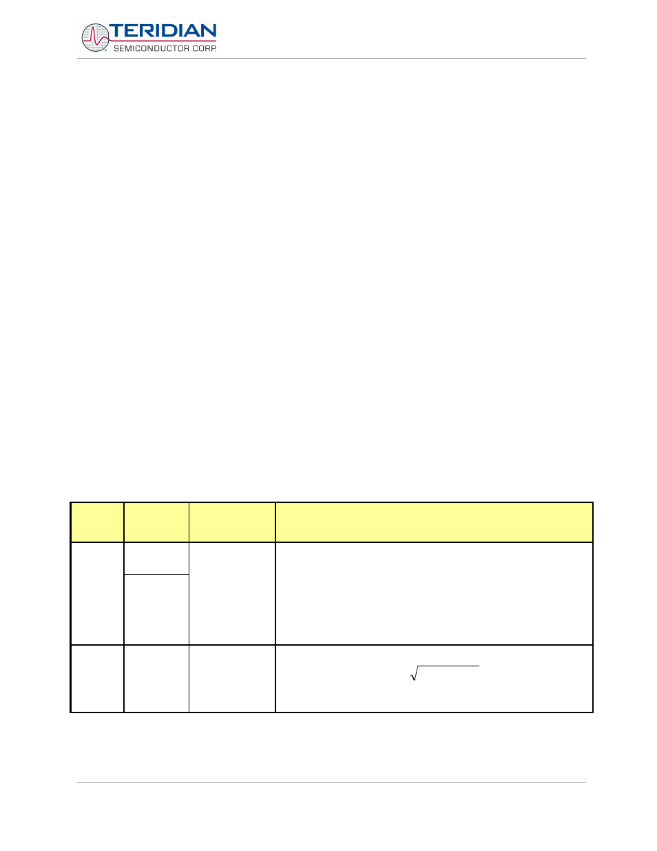
5.10.COMMON MPU ADDRESSES
In the Demo Code, certain MPU XRAM parameters have been given fixed addresses in order to permit easy external
access. These variables can be read via the serial interface, with the )n$ command and written with the )n=xx
command where n is the word address. Note that accumulation variables are 64 bits long and are accessed with )n$$
(read) and )n=hh=ll (write) in the case of accumulation variables.
MPU INPUT PARAMETERS
The parameters listed in Table 5-3, Table 5-4, and Table 5-5 are loaded by the MPU at startup and should not need
adjustment during meter calibration.
XRAM
Word
Address
Default
Value
Name
Description
0x00
8311
(6511)
1536
(6513)
CREEP_THR
For each element, if WSUM_X or VARSUM_X of that element exceeds
CREEP_THR, the sample values for that element are not zeroed.
Otherwise, the accumulators for Wh, VARh, and VAh are not updated
and the instantaneous value of IRMS for that element is zeroed.
6511: LSB = 6.6952*10
-13
VMAX IMAX Wh
6513: LSB = 9.4045*10
-13
VMAX IMAX Wh
Demo Code revision 3.05 offers a separate set of creep-related
variables corresponding to phase B.
0x01
0
CONFIG
Bit 0: Sets VA calculation mode.
0: V
RMS
*A
RMS
1:
2
2
VAR
W
+
Bit 1: Clears accumulators for Wh, VARh, and VAh. This bit need not
be reset.
Revision 2.4
TERIDIAN Proprietary
70 of 137
© Copyright 2005-2006 TERIDIAN Semiconductor Corporation