The 80515 instruction set – Maxim Integrated 71M6513H Power Meter IC Family Software User Manual
Page 103
71M651x Software User’s Guide
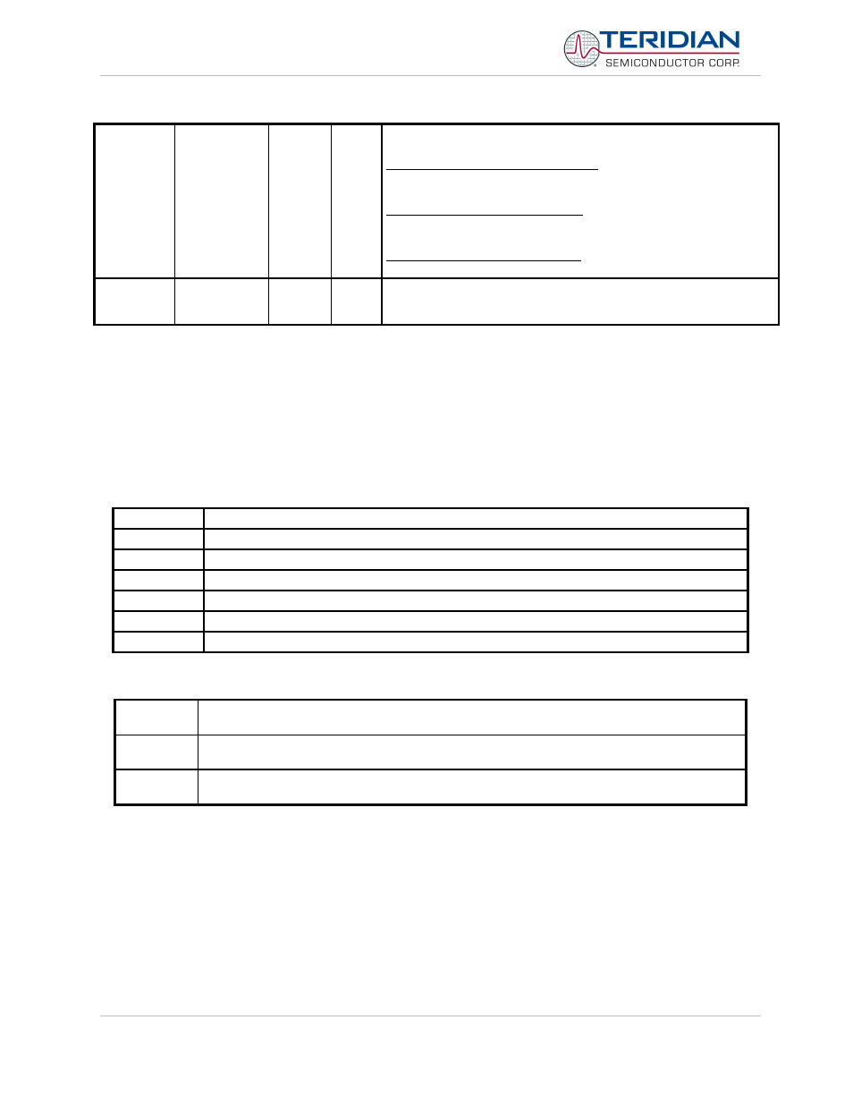
WDI
0xE8
R/W
R/W
W
Only byte operations on the whole WDI register should be used
when writing. This multi-purpose register contains the following bits:
Bit 0 (IE_XFER): XFER Interrupt Flag:
This flag monitors the XFER_BUSY interrupt. It is set by hardware
and must be cleared by the interrupt handler
Bit 1 (IE_RTC): RTC Interrupt Flag:
This flag monitors the RTC_1SEC interrupt. It is set by hardware and
must be cleared by the interrupt handler
Bit 7 (WD_RST):
WD Timer Reset:
The WDT is reset when a 1 is written to this bit.
INTBITS
INT0…INT6
0xF8
R
Interrupt inputs. The MPU may read these bits to see the input to
external interrupts INT0, INT1, up to INT6. These bits do not have
any memory and are primarily intended for debug use
6.2.2. The 80515 Instruction Set
All 80515 instructions are binary code compatible and perform the same functions as they do with the industry
standard 8051. The following tables give a summary of the instruction set cycles of the 80515 Micro controller core.
Table 6-6 and Table 6-7 contain notes for mnemonics used in instruction set tables.
Tables 6-8 through 6-12 show the instruction hexadecimal codes, the number of bytes, and the number of machine
cycles required for each instruction to execute.
Rn
Working register R0-R7
direct
256 internal RAM locations, any Special Function Registers
@Ri
Indirect internal or external RAM location addressed by register R0 or R1
#data
8-bit constant included in instruction
#data 16
16-bit constant included as bytes 2 and 3 of instruction
bit
256 software flags, any bit-addressable l/O pin, control or status bit
A
Accumulator
Table 6-6: Notes on Data Addressing Modes
addr16
Destination address for LCALL and LJMP may be anywhere within the 64-kB of program
memory address space.
addr11
Destination address for ACALL and AJMP will be within the same 2-kB page of program
memory as the first byte of the following instruction.
rel
SJMP and all conditional jumps include an 8-bit offset byte. Range is +127/-128 bytes relative to
the first byte of the following instruction
Table 6-7: Notes on Program Addressing Modes
Revision 2.4
TERIDIAN Proprietary
103 of 137
© Copyright 2005-2006 TERIDIAN Semiconductor Corporation