Block diagram – Maxim Integrated 71M6513H Power Meter IC Family Software User Manual
Page 114
71M651x Software User’s Guide
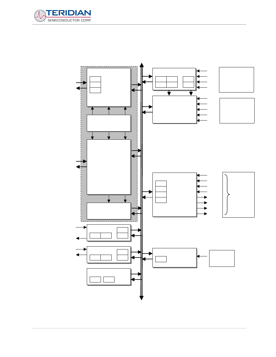
6.3.1. Block Diagram
tf1, ie1
tf0, ie0
cycle
instr
cycle
fetch
instr
cycle
fetch
instr
PORTS
p0
p1
p2
p3
port0i
port2i
port3i
port0o
port1o
port2o
port3o
SERIAL_0
s0con
s0buf
s0rell s0relh
rxd0i
rxd0o
txd0
SERIAL_1
s1con
s1buf
s1rell s1relh
rxd1i
txd1
ie0
ie1
ie2
ircon
ip1
ip0
int2
int3
int4
int5
int6
WATCHDOG_TIMER
wdtrel
swd
instrreg
acc
b
psw
sp
CLOCK_CONTROL
pcon
ckcon
MEMORY_CONTROL
pc
dptr
TIMER_0_1
tl0
tl1
th0
th1
tcon
tmod
t1
t0
int0
int1
in
te
rn
al
s
fr
b
u
s
ISR
CONTROL_UNIT
ALU
RAM_SFR_CONTROL
dptr1
to/from
IRAM
&
SFRs
to/from
XRAMs
&
Prog
Mem
port1i
Figure 6-2: 80515 MPU Block Diagram
Revision 2.4
TERIDIAN Proprietary
114 of 137
© Copyright 2005-2006 TERIDIAN Semiconductor Corporation
DIO gating
registers
(DIO_R)
0
DIO pins
“external”
interrupts