Serial interface 1 modes – Maxim Integrated 71M6513H Power Meter IC Family Software User Manual
Page 120
71M651x Software User’s Guide
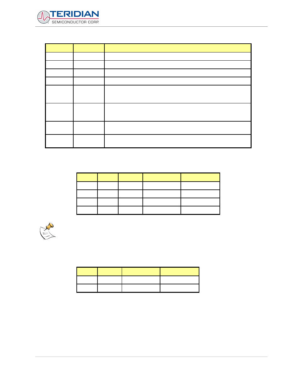
Bit
Symbol
Function
S0CON.7
SM0
Sets baud rate
S0CON.6
SM1
Sets baud rate
S0CON.5
SM20
reserved
S0CON.4
REN0
If set, enables serial reception. Cleared by software to disable reception.
S0CON.3
TB80
The 9
th
transmitted data bit in Modes 2 and 3. Set or cleared by the
MPU, depending on the function it performs (parity check, multipro-
cessor communication etc.)
S0CON.2
RB80
In Modes 2 and 3 it is the 9
th
data bit received. In Mode 1, if SM20 is 0,
RB80 is the stop bit. In Mode 0 this bit is not used. Must be cleared by
software
S0CON.1
TI0
Transmit interrupt flag, set by hardware after completion of a serial
transfer. Must be cleared by software.
S0CON.0
RI0
Receive interrupt flag, set by hardware after completion of a serial
reception. Must be cleared by software
Table 6-28: The S0CON Bit Functions
SM0
SM1
Mode
Description
Baud Rate
0
0
0
shift register
Fclk/12
0
1
1
8-bit UART
Variable
1
0
2
9-bit UART
Fclk/32 or /64
1
1
3
9-bit UART
Variable
Table 6-29: Serial Port 0 Modes
The speed in Mode 2 depends on the smod bit in the Special Function Register PCON when smod = 1,
Fclk/32. See the PCON register description.
Serial Interface 1 Modes
The Serial Interface 1 can operate in 2 modes:
sm
Mode
Description
Baud Rate
0
A
9-bit UART
variable
1
B
8-bit UART
variable
Table 6-30: Serial 1 Modes
Revision 2.4
TERIDIAN Proprietary
120 of 137
© Copyright 2005-2006 TERIDIAN Semiconductor Corporation