Auto-calibration – Maxim Integrated 71M6513H Power Meter IC Family Software User Manual
Page 57
71M651x Software User’s Guide
Auto-Calibration
Auto-calibration is a simplified calibration procedure based on voltage and current measurements. A 0° load angle
(pure resistive load) is assumed. No phase compensation will be performed. Before starting the auto-calibration
process, the user enters the target values for voltage and current that will be applied during the calibration process in
the MPU addresses 0x2029 and 0x202A (see description of aut-calibration in the CLI section). The target values
should be applied to the meter and held constant during the auto-calibration process.
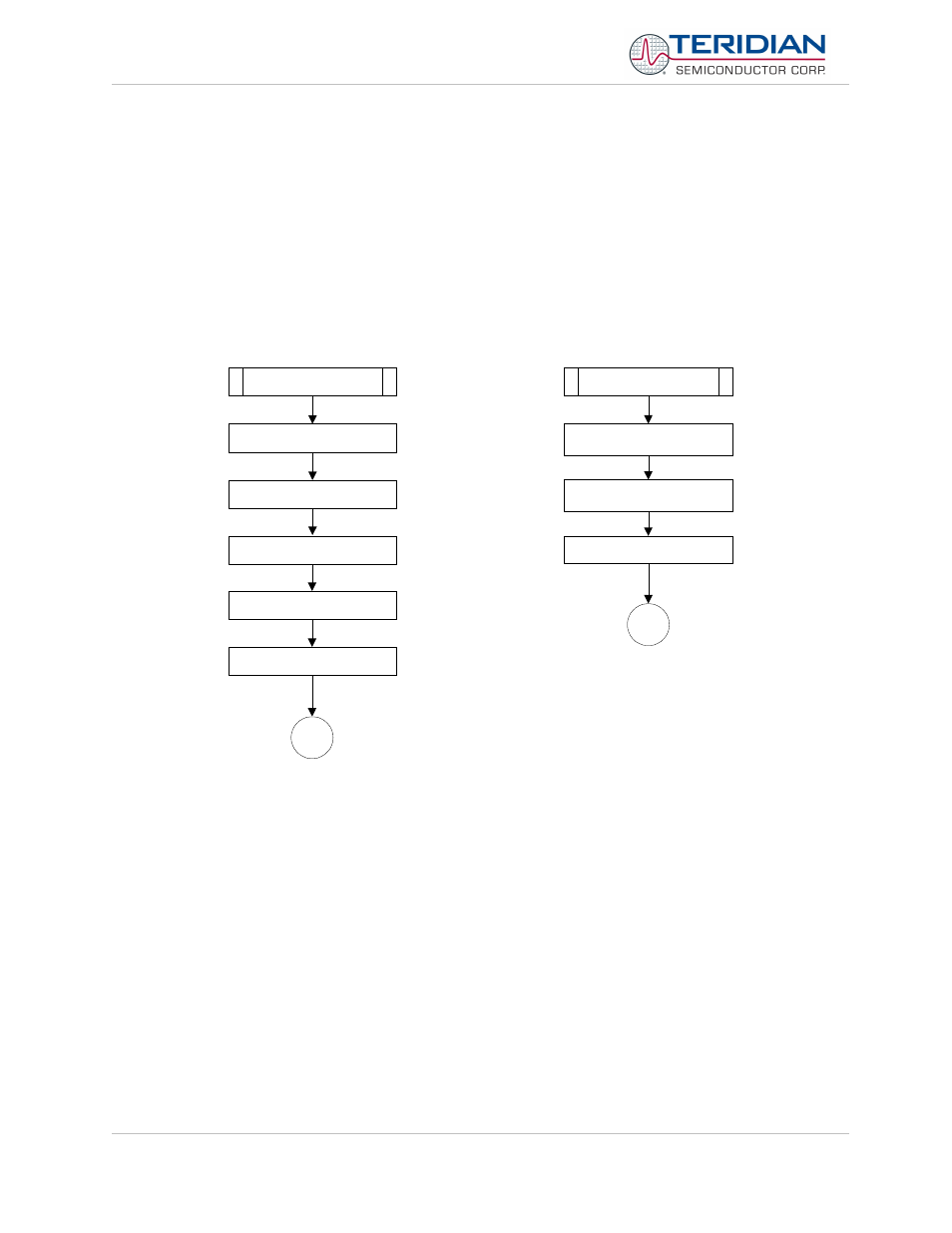
The routines shown in Figure show how auto-calibration is started. The cal_begin() routine starts a state-machine by
setting the flag cal_flag to YES, after setting the calibration factors to default values, recording the calibration
temperature, calculating the temperature compensation coefficients and setting the counter cs for calibration cycles.
The actual stabilization delay, measurement and adjustment phases are managed by separate routines that are
activated by cal_flag being YES and controlled by the variable cs which counts down accumulation intervals.
cal_begin()
END
set calibration values to unity
record calibration
temperature
start count down sequence
calculate PPMC and PPMC2
and write to CE
cal_flag = YES
set calibration values to
unity
END
copy table of starting values
to CE data area
calculate PPMC and PPMC2
and write to CE
populate table with unity
values
Figure 5-15: Auto-Calibration
The processing of the calibration steps is performed by the routine calibration(), which is called in ce_update() when
new data becomes available, i.e. once per accumulation interval. The auto-calibration mechanism functions as a
state-machine, sequenced by the variable “cs”, which is used to count down accumulation intervals:
1) If cs > Scal: The state machine waits for the CE to settle after the unity gain and temperature
compensation data are loaded in the routine cal_begin().
2) If cs = Scal: The variables for each cumulative voltage and current measurement are cleared.
3) If 0 <= cs <= Scal: For two accumulation intervals, prorated measurements of current and voltage are
added to the variables. Using two accumulation intervals covers both chop polarities of temperature
measurements.
4) If cs = 0: This signals the end of the calibration. Cumulative current and voltage measurements are then
used to calculate and set the calibration coefficients for voltage and currents in CE DRAM.
Revision 2.4
TERIDIAN Proprietary
57 of 137
© Copyright 2005-2006 TERIDIAN Semiconductor Corporation