5x drive, Toshiba – Toshiba VF-SX User Manual
Page 31
Attention! The text in this document has been recognized automatically. To view the original document, you can use the "Original mode".
6-4
TOSHIBA
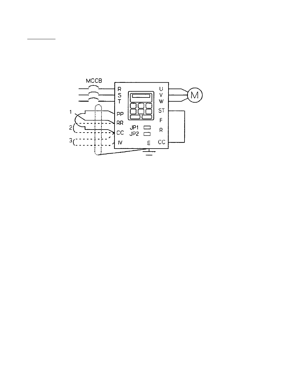
Example 3: To set the operating frequencies with external signals and conduct
the forward/reverse run and decelerating stop from the touchpad.
5X DRIVE
Figure 6.3
Setting: In the parameter group [C S fc ] the
Comand Mode Selection
is set
to 2 (only touchpad input valid). In the same parameter group the
Frequency
Setting node Selection
is set to 1 (only terminal input valid). When the
external signals are input at Terminal IV (see case 3 above), set
Teminal IV
Input,
also in parameter group
[0i~.
5 fc], to 1 (engaged). In this case, the
current input on the IV terminal (4-20mA) will be the standard default setting.
When a 0-5V signal is the required control signal, set the jumper JP2 on the PCB
to V. When a O-IOV signal is to be chosen the input will be from terminals RR
and CC.
When using 0-5V set the jumper JPl on the PCB to 5V.
In Figure 6.3 above:
1. Incoming power is 200-230 volts, three phase, 50 or 60 Hz.
2. Speed reference signal #1 is a potentiometer.
3. Speed reference signal #2 is a O-IOV DC control input signal.
4. Speed reference signal #3 is a 0-20mA, 4-20raA, or 0-5V DC control
input signal.
5. Jumpers JPl and JP2 are shown in their approximate location on the
internal printed circuit board, behind the front cover.