Toshiba 13-3, 2 connection of an ammeter [rh – Toshiba VF-SX User Manual
Page 136
Attention! The text in this document has been recognized automatically. To view the original document, you can use the "Original mode".
TOSHIBA
13-3
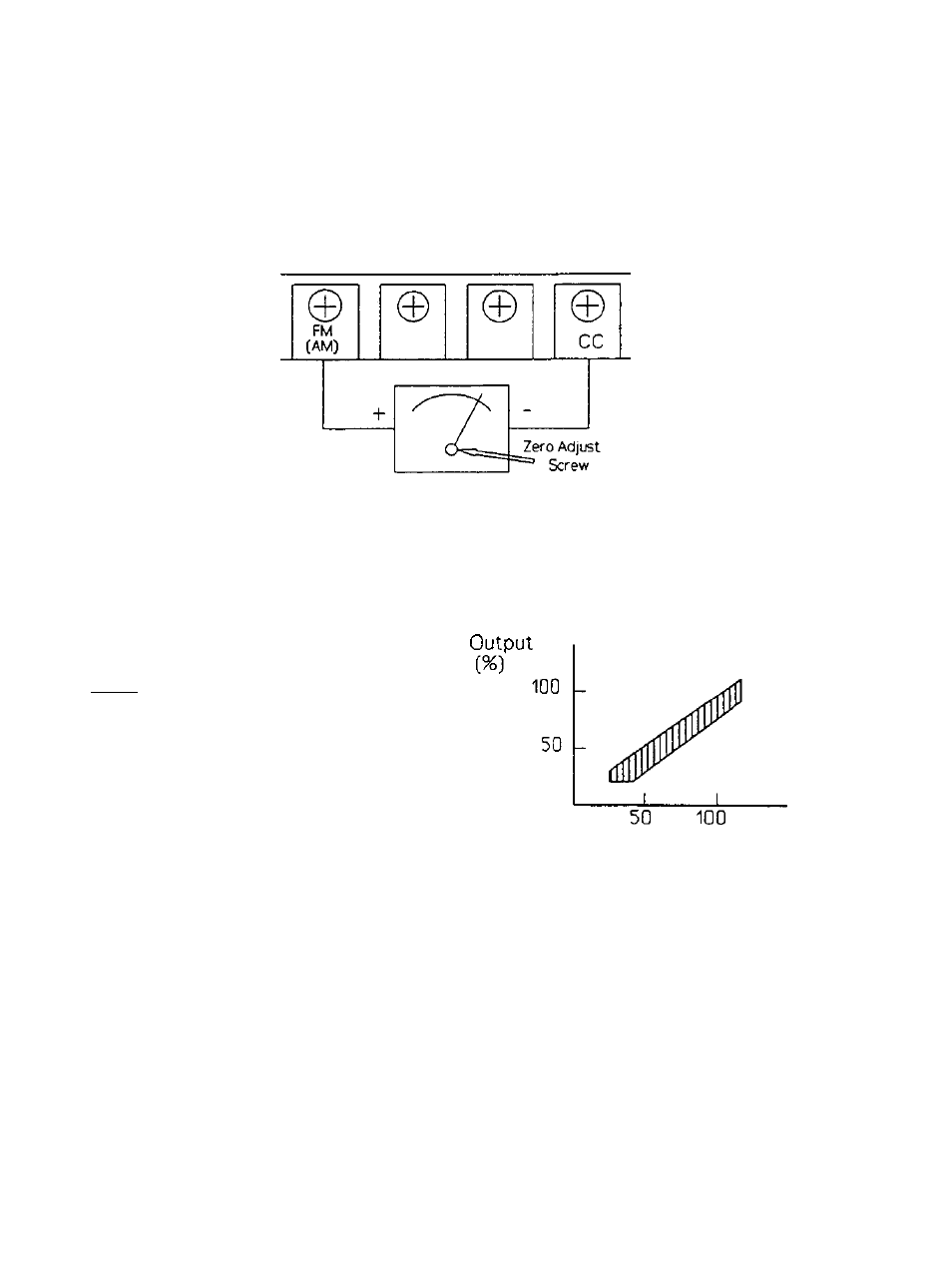
13.1.2 Connection of an Ammeter [RH]
An ammeter can be connected between AM and CC on the control circuit terminal
block. Pay particular attention to the polarity. Also refer to Table 13.1 for
calibration. The connection of the ammeter Is shown In Figure 13.2.
Figure 13.2 Connection of an
Ammeter
Ammeter
NOTE:
The characteristics of the
ammeter output will change slightly
according to the conductive
current as shown In Figure 13.3.
Please take note of this variance,
especially when the drive is lightly
loaded.
Rated Current Ratio
{%)
Figure 13.3 Ammeter Display
Tolerance
The following table shows an example of setting and adjusting a remote frequency
meter. This function is used to calibrate an analog frequency meter or current
meter. The adjustment operations are the same as the parameter setting display
functions. However, the changes with the and keys are not shown on the
LED display, but arc shown with the movement of the meter needle. Adjustment is
carried out by matching the value Indicated by this needle to the LED value.
Refer to the Chapter 7 for the parameter list. An example of programming a
frequency meter Is shown below.