1 inverter trip causes and remedies, 1 inverter trip causes and remedies -2, 2 toshiba – Toshiba VF-SX User Manual
Page 153: O c i, Fl c c, O c e, 0 c 3, O c r, O c l, O p r
Attention! The text in this document has been recognized automatically. To view the original document, you can use the "Original mode".
16-2
TOSHIBA
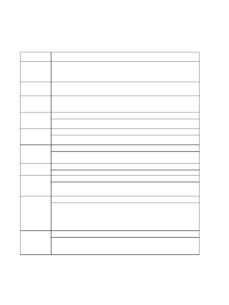
16.1 Inverter Trip Causes and Remedies
The trip codes and potential remedies are shown in the table below.
TABLE 16-1: INVERTER TRIP CAUSES AND REMEDIES
Display
Explanation and Possible Remedy
O C I
OVERCURRENT
TRIP
DURING
ACCELERATION
I
1. Lengthen the acceleration time
[fl
C C ]
setting.
2- Decrease the torque boost rate
o c e
OVERCURRENT TRIP DURING DECELERATION
1. Lengthen the deceleration time
(
c/ E C1 setting.
0 C 3
OVERCURRFNT TRIP DURING DPERATION
1. Sudden change in power required to drive load.
1
2. Reduce load variations.
O C R
PHASE OVERCURRENT TRIP DURING STARTING ICHFCK GTRi
1. Check the main circuit devices. An output device (GTR) is
probably defective and must be replaced.
O C L
LOAD SIDE OVERCURRENT AT STARTUP iCHECK OUTPUT TERMINALl
1. The motor circuit wiring or motor insulation is defective.
2. Check the wiring and insulation.
O P R
OVERVOLTAGE TRIP ON DC BUS DURING DECELERATION
1. Lengthen the deceleration time
[ d E C ]
setting.
2. Install optional regenerative discharge resistor.
1
OVERVOITAGF TRIP ON DC BUS
1. Check the power source for voltage surges or high voltage.
P O F F
UNDERVOLTAGE (See Note 11
1. The input voltage has decreased.
2. Check the power status and input side wiring for proper
input voltage.
O L
MOTOR OVERLOAD TRIP
1. The load may exceed the capability of the drive.
2. The V/f characteristics or torque boost may be
inappropriate. Try increasing the torque boost setting.
3. Increase the Inverter size.
4. Make sure a 50 HZ motor is not being operated with
inverter in 60 HZ mode.
O i r
OVERLOAD TRIP IN REGENERATIVE DISCHARGE BRAKING RESISTOR
1. If possible, do not stop the drive as often.
2. Increase the deceleration time
[ d E C ]
setting.
3.
Increase the regenerative discharge resistance capacity.
TABLE 16-1 (Continued on next page)