Flowshark pulse – ADS Environmental Services FlowShark Pulse QR 775004 A1 User Manual
Page 67
6-22 ADS FlowShark Pulse O&M Manual
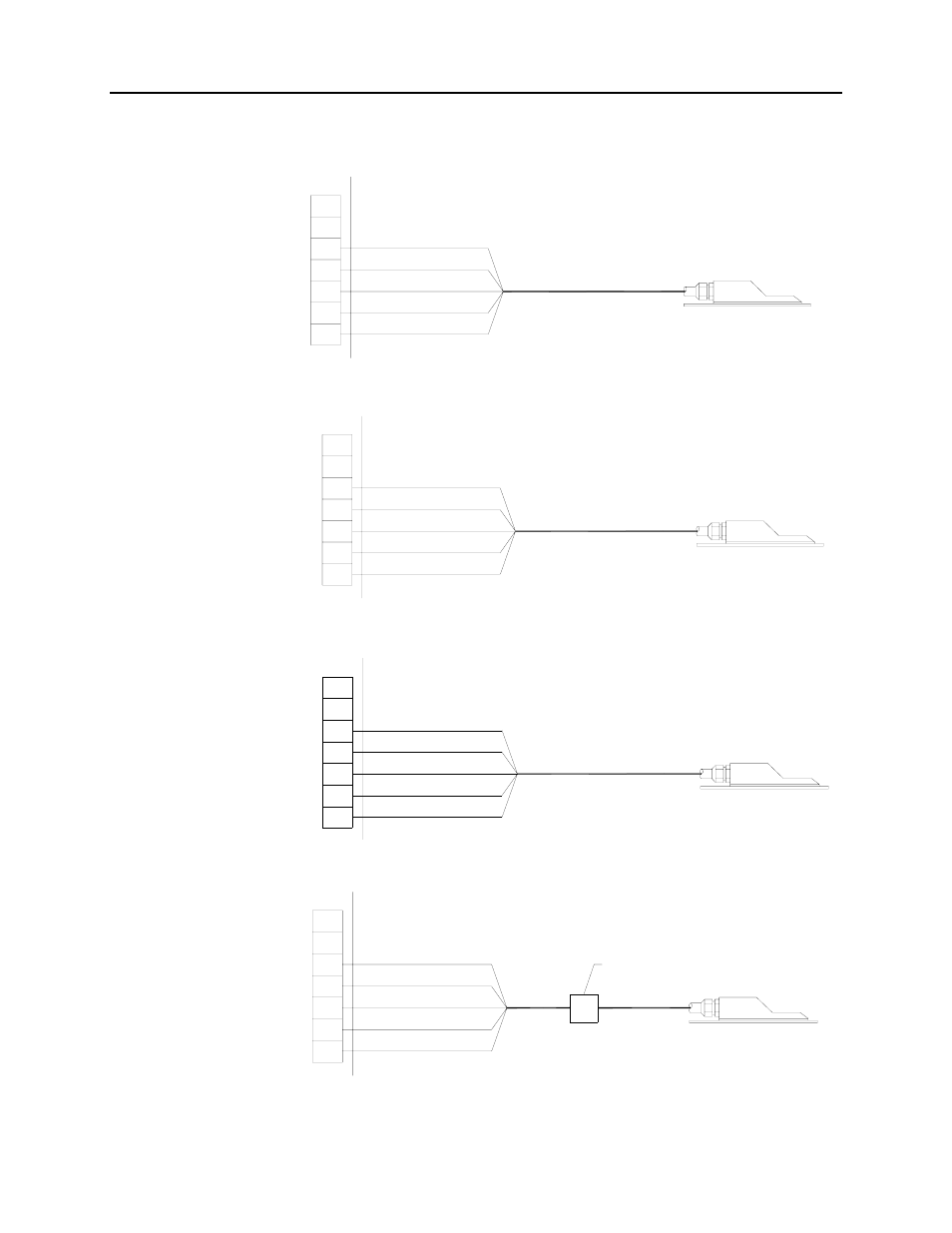
Connect the sensor cable to the transmitter at the termination block. Refer to the
following diagram to connect a flow velocity or water-ultrasonic combi sensor:
not occupied
G1
G2
G3
G4
G5
G6
G7
not occupied
outer shield
supply +
UE-GND
RxTx -
RxTx +
FlowShark Pulse
white
green
blue
red
black (shield, no earth)
8.6 V
LIYC 11Y 2 1.5mm
.
2
+1 2 0.34mm
.
2
.
max. 492.1 ft
combi sensor supporting flow velocity
or water-ultrasonic measurement
Figure 6-27 Connecting a combi sensor supporting flow velocity or water-ultrasonic
not occupied
F1
F2
F3
F4
F5
F6
F7
not occupied
outer shield
supply +
UE-GND
RxTx -
RxTx +
FlowShark Pulse
white
green
blue
red
black (shield, no earth)
8.6 V
LIYC 11Y 2 1.5mm
.
2
+1 2 0.34mm
.
2
.
max. 492.1 ft
combi sensor supporting
flow velocity measurement
Figure 6-28 Connecting a second velocity sensor to the FlowShark Pulse Model 20
not occupied
E1
E2
E3
E4
E5
E6
E7
not occupied
outer shield
supply +
UE-GND
RxTx -
RxTx +
FlowShark Pulse
white
green
blue
red
black (shield, no earth)
8.6 V
LIYC 11Y 2 1.5mm
.
2
+1 2 0.34mm
.
2
.
max. 492.1 ft
combi sensor supporting
flow velocity measurement
Figure 6-29 Connecting a third velocity sensor to the FlowShark Pulse Model 20
not occupied
G1
G2
G3
G4
G5
G6
G7
not occupied
outer shield
supply +
UE-GND
RxTx -
RxTx +
FlowShark Pulse
(white)
(green)
(blue)
(red)
(black; shield, no earth)
8.6 V
A2Y (L)2Y
or similar
max 820.2 ft
connection box with air pressure compensation
(pressure compensation element)
LIYC 11Y 2 1.5mm
.
2
+1 2 0.34mm
.
2
.
+PA 1.5/2.5
max. 98.4 ft
combi sensor supporting flow
velocity & pressure measurement
Figure 6-30 Connecting a flow velocity sensor with an integrated pressure measurement cell