ADS Environmental Services FlowShark Pulse QR 775004 A1 User Manual
Page 59
6-14 ADS FlowShark Pulse O&M Manual
Make sure the horizontal part of the sensor is flush with the pipe wall once installed
(Figure 6-16, far left).
Figure 6-16 Proper pipe insertion sensor installation (left – represents a proper installation; center – represents a
poor installation due to build-up; right – represents a poor installation due to faulty readings or sensor failure)
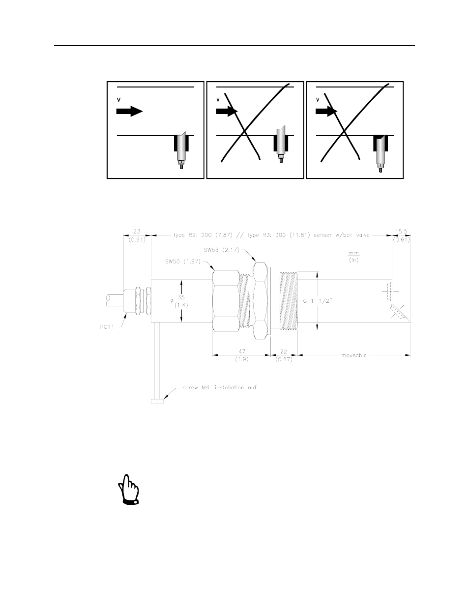
Install the sensor so that the beveled side is facing upstream. The “installation help”
screw (Figure 6-17) assists in proper positioning.
Figure 6-17 Pipe insertion sensor dimensions
When using a pipe insertion sensor with simultaneous ultrasonic depth detection from
bottom up, please install the sensor perpendicular to the flow surface and no more
than ±2 ° from the bottom center of the pipe. Improper installation could produce
erroneous depth measurements under high depth and high flow velocity conditions.
When assembling the pipe insertion sensor, use a special grease for
the stainless steel couplings (DIN 2353, or equivalent). Apply a
small amount of grease to the cap nut thread, threads, cone, and
cutting ring during pre-assembly. The screw joints come pre-
greased from the manufacturer. Purchase additional grease
through ADS, when necessary.