Installation 6-19, Flowshark pulse – ADS Environmental Services FlowShark Pulse QR 775004 A1 User Manual
Page 64
Installation 6-19
not occupied
G1
G2
G3
G4
G5
G6
G7
not occupied
outer shield
supply +
UE-GND
RxTx -
RxTx +
FlowShark Pulse
(white)
(green)
(blue)
(red)
(black; shield, no earth)
8.6 V
A2Y (L)2Y
or similar
max 820.2 ft
connection box with air pressure compensation
(pressure compensation element)
LIYC 11Y 2 1.5mm
.
2
+1 2 0.34mm
.
2
.
+PA 1.5/2.5
max. 98.4 ft
combi sensor supporting flow
velocity & pressure measurement
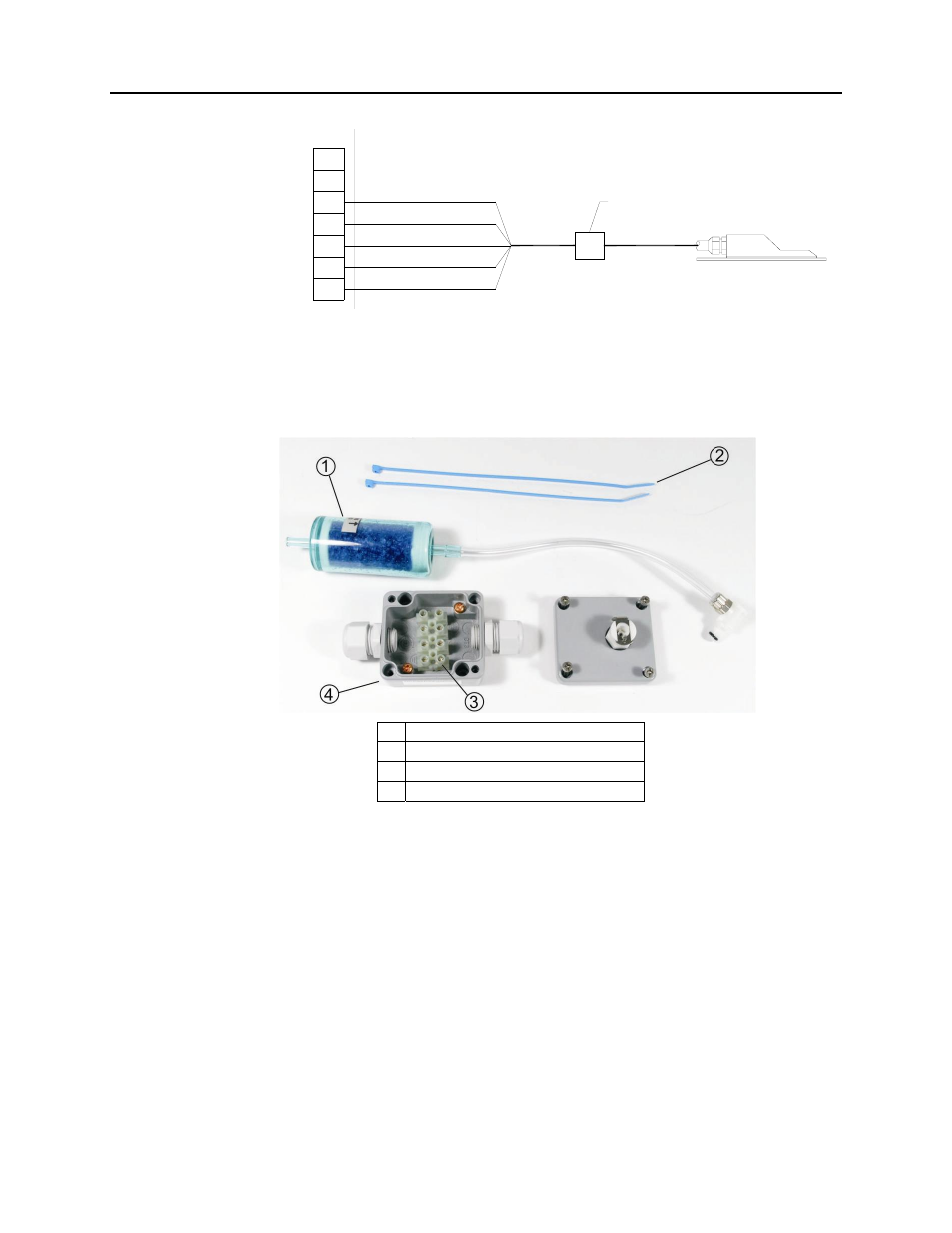
Figure 6-23
Connecting a sensor with pressure measurement cell
The pressure compensation element supplied by ADS consists of a filter element with
an air hose and air plug, metal connection box (including terminal clamps and cable
glands), connection box lid (including integrated, self-locking socket for the air hose
plug), and 2 cable clips (Figure 6-24).
1
Filter element with air hose and air plug
2 Cable
clips
3 Terminal
clamps
4 Connection
box
Figure 6-24 Components of air compensation element
Connect the 5-wire cable coming from the combi sensor to the terminal clamp strip in
the connection box, with each individual wire connecting to a separate terminal
clamp. For this application, connect only the power supply wires (red + blue) and the
signal bus lines (white + green) to the terminal clamp strip. Connect the cable shield
(black) to one of the shield connection screws in the box (Figure 6-25).