Flo w sha rk pulse, Ex ar ea, Installation 6-5 – ADS Environmental Services FlowShark Pulse QR 775004 A1 User Manual
Page 50: Ab c
Installation 6-5
Flo
w
Sha
rk Pulse
45
67
8
1
2
3
9
10
11
12
13
14
15
16
17
18
19
20
21
45
6
7
8
2
3
9
101
1
12
13
14
1
51
6
1
71
8
1
9
2
02
1
45
67
8
9
10
1
1
GN
D
CO
M
RT
S
Tx
D
D
I3
DI
4
G
N
D
AI
4
AI3
sh
ie
ld
GN
D
A
O
3
AO4
G
N
D
L1
N
P
E
DC
-
AO
A
O
blank
CT
S
RxD
D
I1
DI
2
G
N
D
A
I2
AI
1
G
ND
A
O
1
A
O2
G
N
D
DI
AI
A
O
1/
2
24
V
DC
+
+
BUS
B
US
PE
+
24
V
DC
+
+
GN
D
DC
-
10-36V
auxiliary supply-
max. 100mA +
R 500
Lmax
0/4-20mA
I
23
0V
A
C
/2A
ma
x
cos
=
0.9
re
la
y ou
tp
ut
s
1-
5
(f
or
ty
pe
S3 on
ly)
relay 1+
2
occup
ied
pow
er
supply
ser
ial
dig
ita
l inpu
ts
a
na
log
ana
log
inter
face
(fo
r ty
pe
M3 on
ly
)
inputs
(A
I2
-4
ou
tp
ut
s
(A
O3
-4
M
3 on
ly
)
M
3
only)
a
b
c
D
A
D
A
D
A
D
A
a(b)16
a(b)17
a(b)18
a(b)19
a(b)20
a(b)21
a(b)12
a(b)13
a(b)14
mo
dem
an
alo
g
E
th
e
rnet
or
IS
D
N
a8
c8
b8
a4
c4
b4
cl
am
p
line
OF
F
ON
230
V AC
24V
D
C
D1
D2
D3
D4
D5
D6
D7
D8
D9
E1
E2
E3
E4
E5
E6
E7
F1
F2
D3
F4
F5
F6
F7
G1
G2
G3
G4
G5
G6
G7
E
/F
/G 6+
7
no
t o
ccu
pi
ed
co
nn
ec
to
r p
lu
g
flow
ve
lo
ci
ty
se
ns
or
(s
)
a
ir ult
rasonic
an
d
ex
te
rn
al
2
-w
ire
le
ve
l
measir
ement
Ex
ar
ea
--
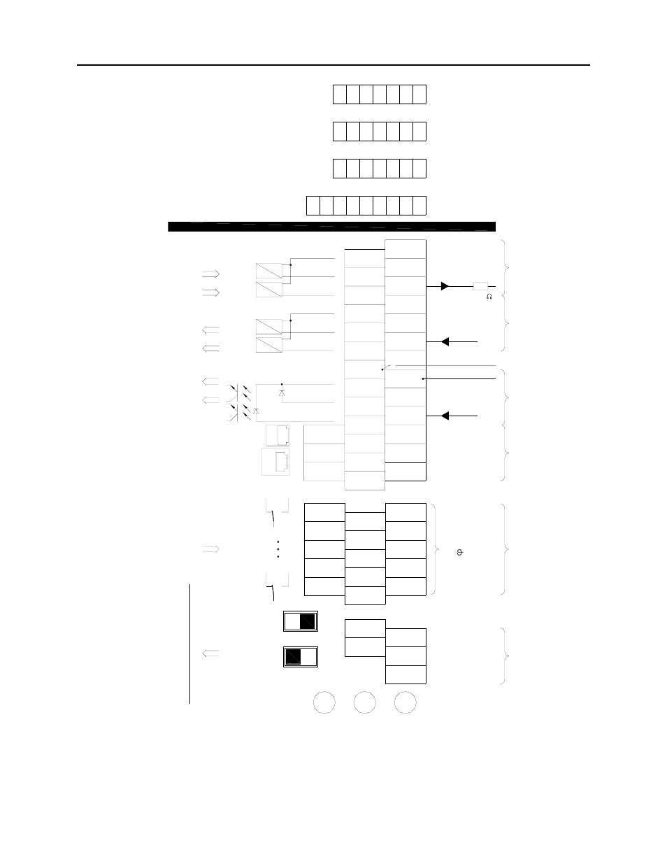
GND potentials isolated from each other: DE1/2, DC-, AE1 ... 4, AA1 ... 4
Internal wiring: b2 + b15; b3 + a14
Figure 6-2 Wiring diagram for FlowShark Pulse wall mount enclosure