4 connection of the suppressor module – Metrohm 761 Compact IC User Manual
Page 53
2.8 Suppressor module
761 Compact IC
43
2.8.4
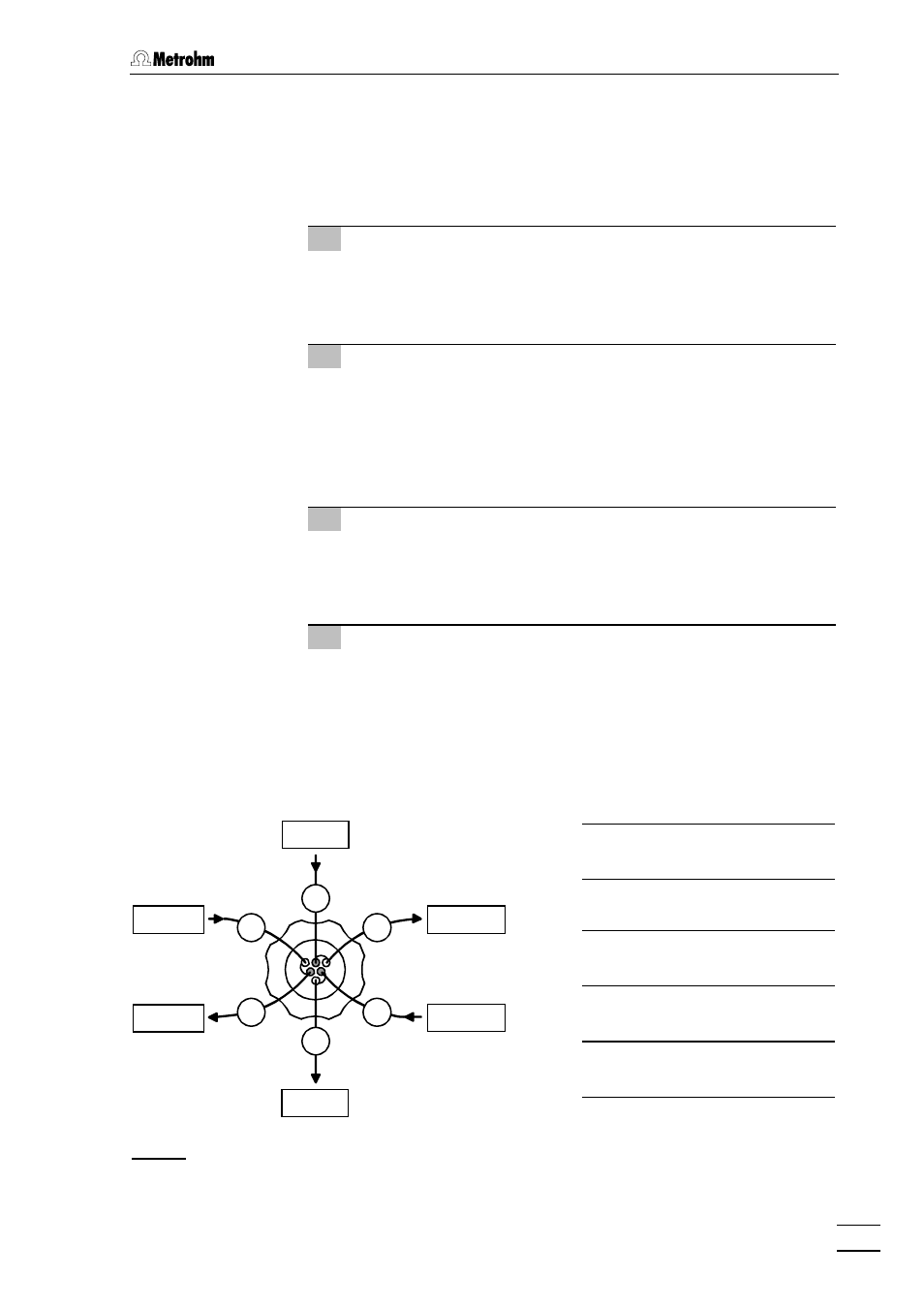
Connection of the suppressor module
The three inlets and outlets numbered 1...3 on the suppressor module
47 each have 2 permanently mounted PTFE capillaries, which must be
connected as described as follows (see Fig. 16 and Fig. 18).
1 Inlet capillary for eluent
•
Screw inlet capillary 96 marked with "Eluent" of suppressor
module 47 to outlet end of separating column 81 using a
6.2744.010 Compression fitting.
2 Outlet capillary for eluent
•
Screw outlet capillary 97 marked with "Detector" of suppres-
sor module 47 to coupling 33 using a 6.2744.010 Compres-
sion fitting.
•
Screw inlet capillary 45 of detector block 46 to other end of
coupling 33.
3 Inlet capillary for H
2
SO
4
•
Attach inlet capillary 99 marked with "H
2
SO
4
" of suppressor
module 47 using a 6.2744.010 Compression fitting to the filter
unit PEEK 36 connected to the rear pump tubing 92.
4 Outlet capillary for H
2
SO
4
•
Pull outlet capillary 101 marked with "Waste" of the suppres-
sor module 47 from below through one of the openings 13
out of the inner compartment of the 761 Compact IC.
•
Lead outlet capillary 101 to a sufficiently large waste con-
tainer and fix it in place.
1
3
2
96
100
98
97
99
101
Fig. 18:
Connections at suppressor module
96
Suppressor inlet
capillary for eluent
97 Suppressor outlet
capillary for eluent
98 Suppressor inlet
capillary for H
2
O
99 Suppressor inlet
capillary for H
2
SO
4
100 Suppressor outlet
capillary for H
2
O
101 Suppressor outlet
capillary for H
2
SO
4
Eluent
H
2
O
Detector
Waste
Waste
H
2
SO
4