Rockwell Automation SA500 Drive Configuration and Programming User Manual
Page 88
4-2
SA500 Drive Configuration and Programming
Executive software. Like Control Block tasks on AutoMax Processors, UDC tasks can
include a number of BASIC language statements and functions; however, those that
allow task suspension or delay are not supported.
UDC tasks are created, compiled, loaded, and monitored in the same way as Control
Block tasks for AutoMax Processors. UDC task variables can be monitored, set,
tuned, and forced like AutoMax task variables. Note that the UDC module is accessed
for monitoring an loading through the serial port on the leftmost AutoMax Processor
(or over the DCS-NET network), which is used for all connections to the rack.
Any UDC dual port register that is to be used in a UDC task must be defined as
COMMON in the task. Recall that UDC dual port memory registers are either reserved
for a specific use such as rail I/O data or available for application-specific purposes to
the programmer. Registers that are not specifically identifier in one of these two ways
in the Programming Executive software or in this instruction manual must not be
written to by either the UDC or AutoMax tasks because they are being used by the
operating system.
Generally, the common variables on the UDC module are either written to only by
AutoMax tasks (“read only” to UDC tasks), or they are written to only by a UDC task
(“read only” to AutoMax tasks). The former are typically variables that control an
action, e.g., requesting the minor loop to run, and the latter are typically status
variables, e.g., indicating the status of the fiber-optic communication link.
UDC tasks can access only the UDC module’s own dual port memory. They cannot
access other variables in the rack unless an AutoMax task writes those variable values
to the application-specific registers in the UDC dual port.
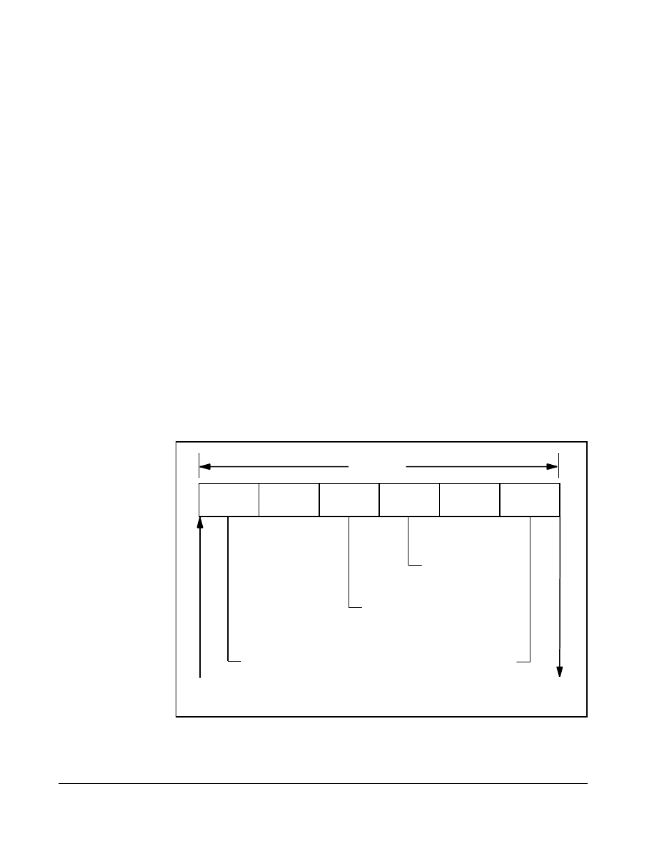
Figure 4.1 illustrates one UDC task scan.
.
Figure 4.1 – UDC Task Scan
Input A
Run A
Output A
Input B
Run B
Output B
UDC Scan*
Fe
edback From
PM
I
C
o
m
m
and to
PM
I
*Task B can act on Task A outputs within a scan.
Latch “every scan”
registers that are
inputs to task B
Write “every scan”
registers that are
outputs from task A
Latch “every scan”
registers that are
inputs to task A
Write “every scan”
registers that are
outputs from task B