Rockwell Automation SA500 Drive Configuration and Programming User Manual
Page 14
2-4
SA500 Drive Configuration and Programming
Note that you cannot attach a Local I/O Head to the PMI’s rail ports. You can,
however, mix input and output modules in a Digital I/O Rail. You can also mix
rail types, i.e., add both a Digital I/O Rail and an Analog Rail (rail mode only)
to a PMI.
Select the Configure Variables option from the Configure menu in order to
configure the variables for the attached rails. Zoom out to return to the PMI
screen.
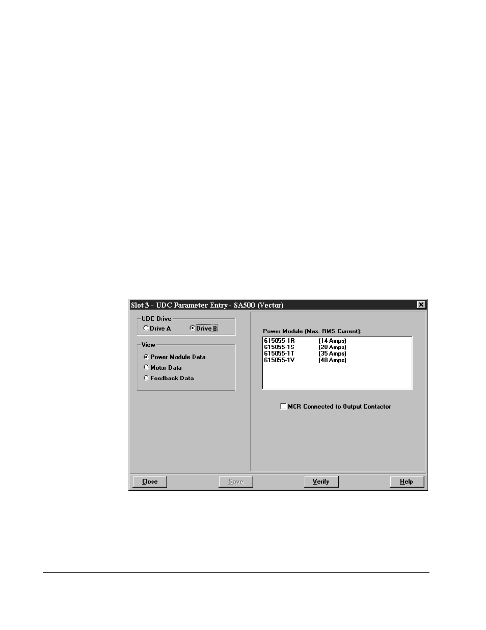
Step 3. Use the Configure Parameters option to access the Parameter Entry
screens. Assuming you are configuring an SA500 drive, there are three
screen displays: Power Module Data, Motor Data, and Feedback Data. See
figure 2.1. Each of these screens is described in detail in the following
sections (section 2.3 for the brushless regulators, section 2.4 for the vector
regulators).
Note that the AutoMax slot number of the UDC module is shown at the top of
the screens. The screens prompt for specific information depending upon
the item that is being configured.
Step 4. When you have made entries for the drive parameters on all of the parameter
entry screens, you should select the “Verify” option displayed at the bottom of
the screen. If any of the values you entered are invalid or out of range, the
parameter that is invalid will be highlighted so that you can change the value.
When you have finished entering drive parameters, select “Save” to save the
values to the database.
.
Figure 2.1 – SA500 Drive Parameter Entry Screen (Vector)