Rockwell Automation SA500 Drive Configuration and Programming User Manual
Page 39
Configuring the UDC Module’s Registers
3-7
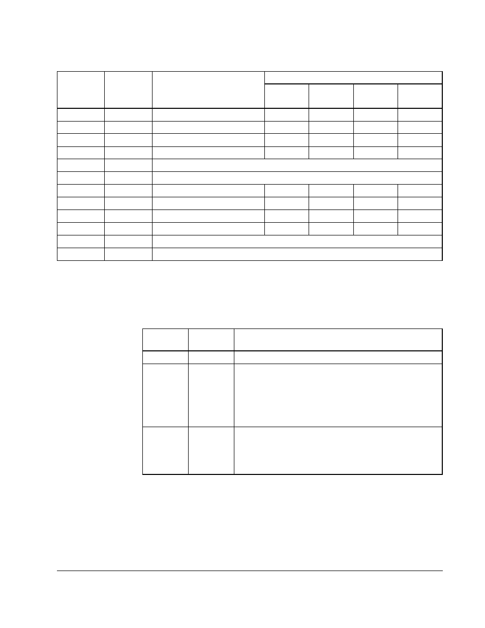
Table 3.3 – Rail I/O Port Registers
Drive A
Registers
Drive B
Registers
Port and Channel
Rail Type and Signal
4 Output
1
4 Input
2
2 Input
3
2 Output
Digital
I/O
4
0
12
Port 0 - Channel 0
Output 0
Input 0
Output 0
Digital
1
13
Port 0 - Channel 1
Output 1
Input 1
Output 1
N/A
2
14
Port 0 - Channel 2
Output 2
Input 2
Input 2
N/A
3
15
Port 0 - Channel 3
Output 3
Input 3
Input 3
N/A
4
16
Port 0 - Fault Register (Tables 3.4 - 3.6)
5
17
Port 0 - Check Bit Fault Count Register (Tables 3.4 - 3.6)
6
18
Port 1 - Channel 0
Output 0
Input 0
Output 0
Digital
7
19
Port 1 - Channel 1
Output 1
Input 1
Output 1
N/A
8
20
Port 1 - Channel 2
Output 2
Input 2
Input 2
N/A
9
21
Port 1 - Channel 3
Output 3
Input 3
Input 3
N/A
10
22
Port 1 - Fault Register (Tables 3.4 - 3.6)
11
23
Port 1 - Check Bit Fault Count Register (Tables 3.4 - 3.6)
1. 4-Output Analog Rail Module (M/N 61C365, 61C366)
2. 4-Input Analog Rail Module (M/N 61C345, 61C346)
3. 2-Output/2-Input Analog Rail Module (M/N 61C350, 61C351)
4. Digital I/O Rail (M/N 45C1), Thumbwheel Switch Input Module (M/N 45C630), or LED Output Module (M/N 45C631
Table 3.4 – Fault Register and Check Bit Fault Counter Register
Usage for a Digital I/O Rail or 4-Output Analog Rail Module
Drive A
Registers
Drive B
Registers
Description
4
16
Port 0 Fault Register
10
22
Port 1 Fault Register
Bit 8: No device plugged into a configured port
Bit 9: Bad ID code: device other than rail plugged into port
Bit 10: Bad rail communication check bits received
Bit 11: PMI interface is not ready
5
17
Port 0 Check Bit Fault Counter Register
11
23
Port 1 Check Bit Fault Counter Register
These registers can be reset by setting bit 9 of the Drive
Control register (100/1100)