2 entering the drive parameters – Rockwell Automation SA500 Drive Configuration and Programming User Manual
Page 12
2-2
SA500 Drive Configuration and Programming
Step 4. Select a product type and a regulator (control) type for both drive A and
drive B. See the following section for regulator restriction rules. The
remainder of this chapter assumes that you have selected an SA500 product
type and have chosen one of the following regulator selections: Vector,
Brushless, Vector - Speed Loop Enhanced, or Brushless - Speed Loop
Enhanced.
Note that if your application requires the use of the constant power feature,
you must select the Vector - Speed Loop Enhanced regulator.
Whether you are configuring Brushless, Brushless - Speed Loop Enhanced,
Vector, or Vector - Speed Loop Enhanced, the block task must contain the
Constant Power Calibration local tunable variables (STATOR_IZxE2%, see
Appendix B) or an error will occur when you try to download the tasks.
Step 5. Select OK to add the UDC module to the rack and return to the Rack
Configuration screen.
Rules for Configuring/Selecting Drives for the UDC Module
1.
The A and B drives do not both have to be used. You can configure only one.
2.
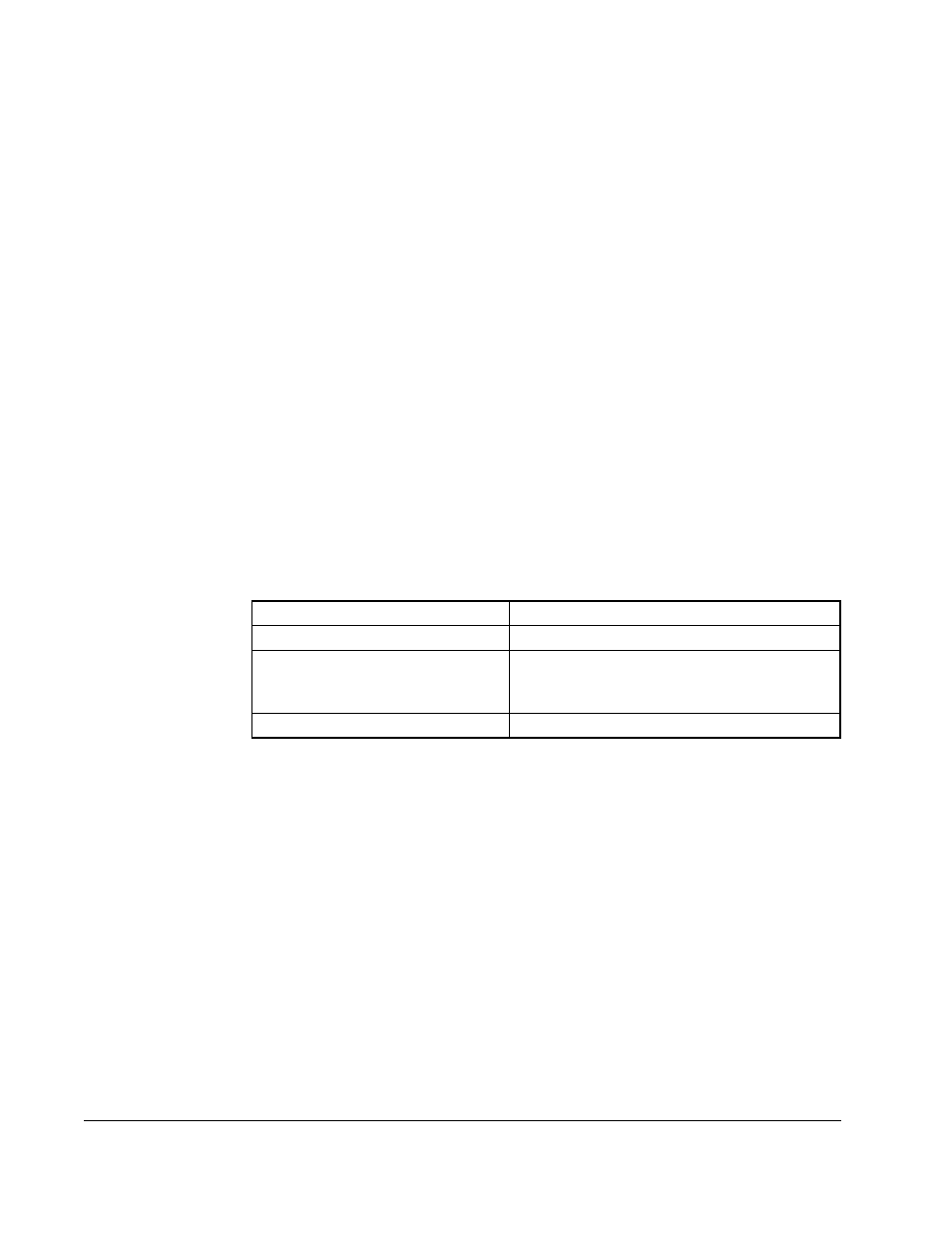
Your A/B drive type combination is restricted only if you select an SD3000
(12-Pulse) drive, an SF3000 drive, or an SA3000 Parallel Inverter for either drive A
or drive B. For these products, you are restricted to the drive type combinations
shown in table 2.1. All other drive type combinations are allowed.
2.2
Entering the Drive Parameters
Drive parameters are application-specific data that describe your installation’s Power
Modules, feedback devices, and motors. This information is loaded to the UDC
module, which in turn automatically downloads it to the PMI when the two are first
connected over the fiber-optic link. This information is also stored off-line with the
Programming Executive. Note that the drive parameters will be retained by the UDC
module during a STOP ALL fault or command to the rack.
Once a UDC module has been added to the rack, use the Zoom In command to begin
entering the drive parameters. See the AutoMax Programming Executive instruction
manual for more information on Zooming in and out.
Table 2.1 – Restricted Drive Type Combinations
If you choose for Drive A . . .
Then your choices for Drive B are . . .
SD3000 (12-Pulse)
SD3000 12-Pulse Auxiliary
SF3000
No PMI Attached
SD3000 (6-Pulse)
SF3000
SA3000 Parallel Inverter
SA3000 Parallel Inverters Auxiliary