Rockwell Automation SA500 Drive Configuration and Programming User Manual
Page 17
Configuring the UDC Module, Regulator Type, and Parameters
2-7
•
Motor Overload Ratio (%) (Range: 100 to 400)
The motor overload ratio is used in calculating the torque limit. Enter the value in
percent. A warning will be generated if the value entered is not within the limits of
the following equation:
Rated Motor Amps
∗
Motor Overload
÷
100
≤
Power Module Amps
•
Stator Inductance (mH) (Range: 0.01 to 50.0)
The stator inductance is used to calculate the amplitude of the triangle wave that
produces the PWM output to the motor.The smaller the inductance, the higher the
gain of the current loop inside the vector and brushless control algorithm. This
parameter has been calculated specifically for the motor selected.
If the motor to be used is not on the list, see Appendix F for stator inductance
calculation. Enter the value in millihenries. The resolution is 0.01mH.
•
Torque Gain (Nm/Amp) (Range: 0.001 to 9.999)
The torque gain is used to scale the torque loop. The higher the torque gain, the
more torque that will be produced for a given reference. This parameter has been
calculated specifically for the motor selected.
If the motor to be used is not on the list, see Appendix F for torque gain calculation.
Enter the value in Newton Meters per Amp. The resolution is 0.001 Nm/Amp.
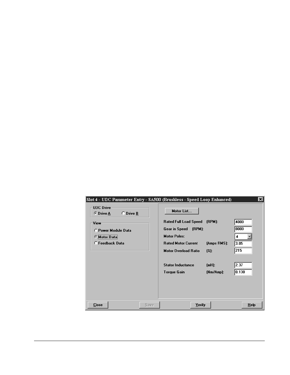
2.3.3 Motor Data Screen (Brushless - Speed Loop Enhanced)
The Motor Data parameter screen allows you to select the motor you are using. You
must select your motor from the list displayed. See figure 2.4.
Figure 2.4 – Motor Data Parameter Entry Screen (Brushless - Speed Loop Enhanced)