Rockwell Automation 1746-HSRV SLC Servo Control Module User Manual User Manual
Page 94
Publication 1746-6.1.2 - July 2000
Setting Up Your SLC Servo Module 7-15
AC line conditions. If you don’t meet these conditions, you experience
excessive error faults during high speed operation. You must select
the proper motor, drive, and gearing to satisfy the above requirement
for the application. AC power to the motor drive can go as low as 85%
of the nominal input voltage. To allow for axis operation at low line
conditions, use a power line factor between 0.85 and 1.0. Select a
power line factor based on motor and drive vendor specification.
The maximum low line operating speed (from the motor data sheet
plus gearing) can be calculated by performing the following:
Operating at maximum speed that you want, select a DAC output
saturation speed greater than the operation speed that you want. A
reasonable percentage of maximum is approximately 105%. The DAC
output saturation speed is the maximum speed for the axis, and we
calculate it as follows:
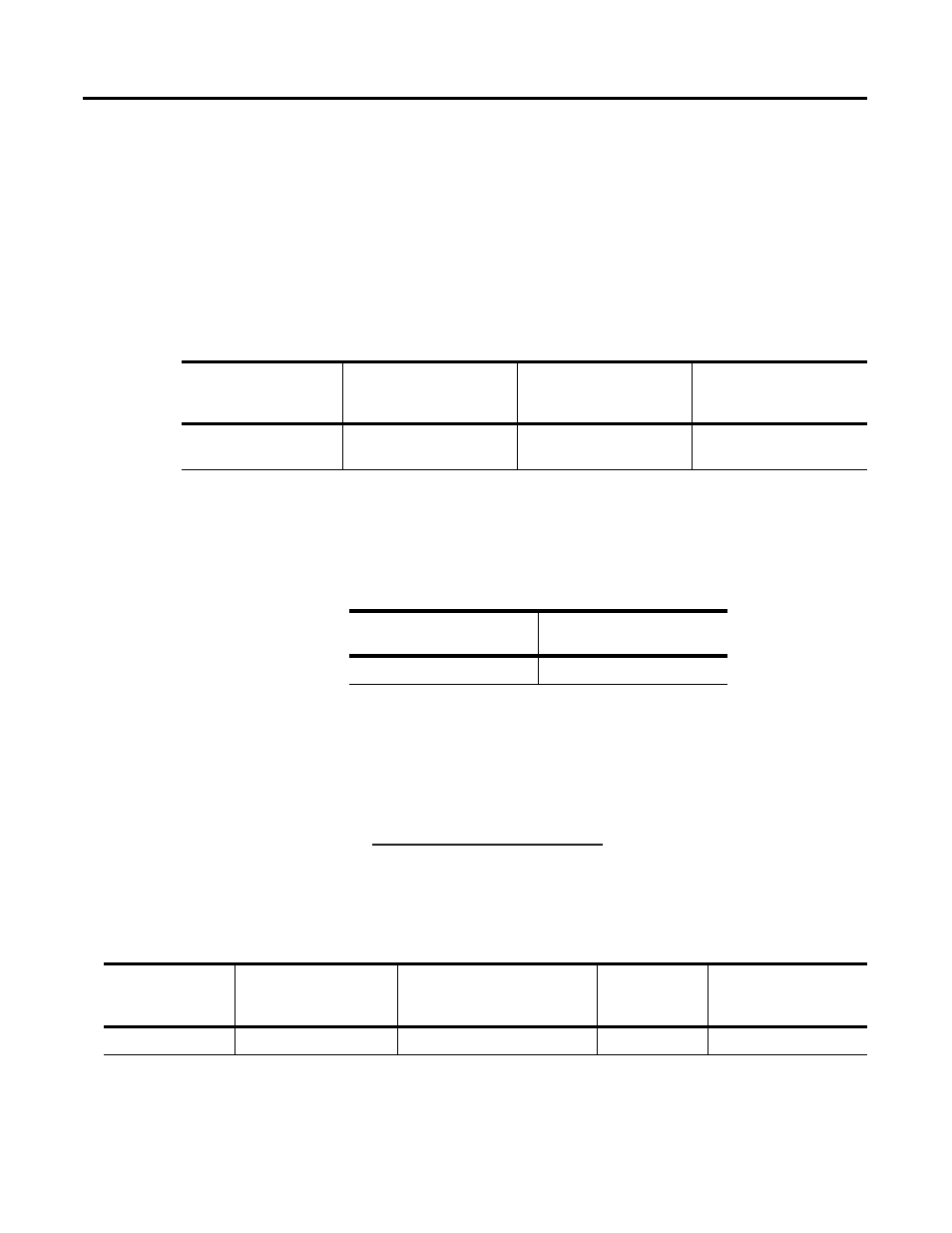
In the example below, select a 3000 rpm motor for use with the
previous example in this section. Compute the maximum operating
speed using the following equation:
Maximum operating
speed for the axis is
equal to:
Multiplied by:
Multiplied by:
Multiplied by:
Power line factor
Maximum motor rpm
Output revolutions/
input revolutions
1/pitch
Maximum operating speed
is equal to:
Multiplied by:
1.05
Maximum speed that you want
(Power Factor)
*
(RPM
*
(Encoder lines
*
4)
Counts per Position Units
=
Maximum Operating Speed
Power factor:
Multiplied by:
revolutions per minute
(RPM)
Multiplied by:
Encoder lines * 4
Divided by:
Counts per
position units
Equals maximum
operating speed:
0.85
3000
4000
60000
170 (ipm)