System module servo input wiring board, Estop, Drive enable drive – Rockwell Automation 1746-HSRV SLC Servo Control Module User Manual User Manual
Page 69
Publication 1746-6.1.2 - July 2000
5-26 Wiring the SLC Servo Module
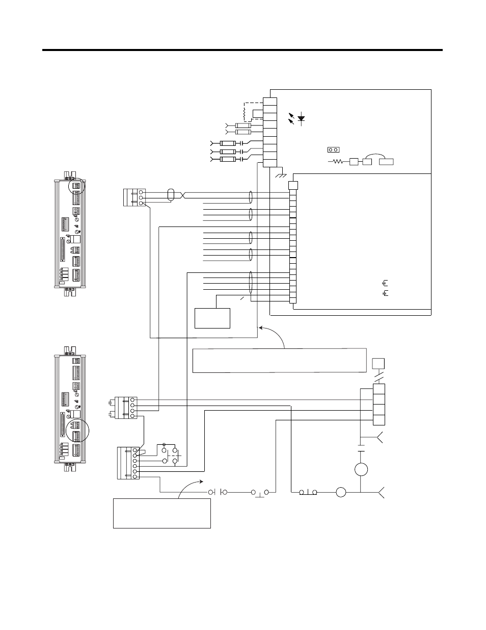
Figure 5.22 Wiring Diagram for 1394 Systems
TB1
+24
S TR IN G IN
R E S. P B
R E S. P B
R E SE T
ST R ING O U T
Axis Overtravels
(if not directly coupled)
Motor
Thermals
16
17
18
19
TB2
Contactor EN
Contactor EN
DROK
DROK
M1
CR1
CR1
STOP
1
2
3
4
5
6
7
8
9
10
11
12
13
14
15
16
17
18
19
20
DC+
COL
INT
W1
W2
U
V
W
PE
FAULT RESET
ANALOG OUT 1
A0 VREF +
A0 VREF -
SHIELD
SHIELD
SHIELD
SHIELD
A0 ENABLE
A0 TOREF +
A0 TOREF-
A2 VREF +
A2VREF -
A2 TOREF +
A2 TOREF -
A2 ENABLE
ANALOG OUT 2
ANALOG COM
COM
CHASSIS
To ground bar
if not grounded
elsewhere
COMMON
DS1
SOLID GREEN = BUS UP, AXIS ENABLED
FLASHING GREEN = BUS UP, AXIS NOT ENABLED
FLASHING RED/GREEN = READY, BUS NOT UP
FLASHING RED = FAULT
SOLID RED = HARDWARE FAILURE
P1
J26
J27
GND3
DC MINUS BUS
System Module
Servo Input Wiring Board
CONTACTOR ENABLE RELAY
RATED AT 115V AC, 24V DC, 1A INDUCTIVE
DRIVE O.K. RELAY
RATED AT 115V AC, 24V DC, 1A INDUCTIVE
OPTIONAL EXTERNAL SHUNT
USER-SUPPLIED 24V AC RMS OR
24V DC. (NON-POLARIZED)
THREE PHASE INPUT
380 - 460V AC RMS
M1
INPUT FUSING
Estop
24 AC/DC
or
120V AC
50/60 Hz
Drive Enable
Drive
DRIVE
DR RET
SHLD
Important:
This connection is required if the system is grounded
at one end only. We recommend grounding the
system at the drive amplifier only.
Important:
Do not directly connect
Motor Thermals. They
must be isolated with
a relay.