Configuration parameters, Feedback parameters – Rockwell Automation 1746-HSRV SLC Servo Control Module User Manual User Manual
Page 105
Publication 1746-6.1.2 - July 2000
7-26 Setting Up Your SLC Servo Module
Configuration Parameters
This section provides information to help you set discrete and
floating-point parameters for the SLC Servo Module. These parameters
are grouped according to their function:
•
Feedback parameters
•
Servo loop parameters
•
Motion parameters
•
Axis parameters
•
Homing parameters
•
System parameters
You can determine these parameters by using the integration
procedure described in the Setting Up Your SLC Servo Module chapter.
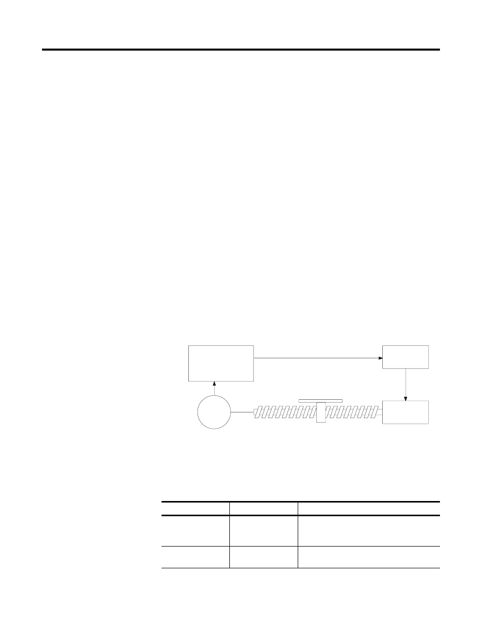
Feedback Parameters
Feedback parameters define the position feedback sent to the SLC
Servo Module. This position feedback is for the axis controlled by the
SLC Servo Module. Use Figure 7.3 and the following table to see how
feedback parameters work with the servo loop parameters.
Figure 7.3 How Feedback Parameters Work with Servo Loop Parameters
The following table provides the name, file location, and a brief
description of the Feedback parameters. For more detailed
information see Appendix A of this manual.
SLC Servo Module
Drive
Motor
Encoder
Encoder Lines (M0, w4-5)
Counts Per Position Unit (M0, w6-7)
Name
Location
Description
Encoder Lines
M0:s.4,5
Specifies the number of lines per revolution of
the input shaft. This parameter would be in the
encoder specification sheet.
Counts per Position
Unit
M0:s.6,7
Specifies the number of encoder edges per
position unit.