Rockwell Automation 1746-HSRV SLC Servo Control Module User Manual User Manual
Page 107
Publication 1746-6.1.2 - July 2000
7-28 Setting Up Your SLC Servo Module
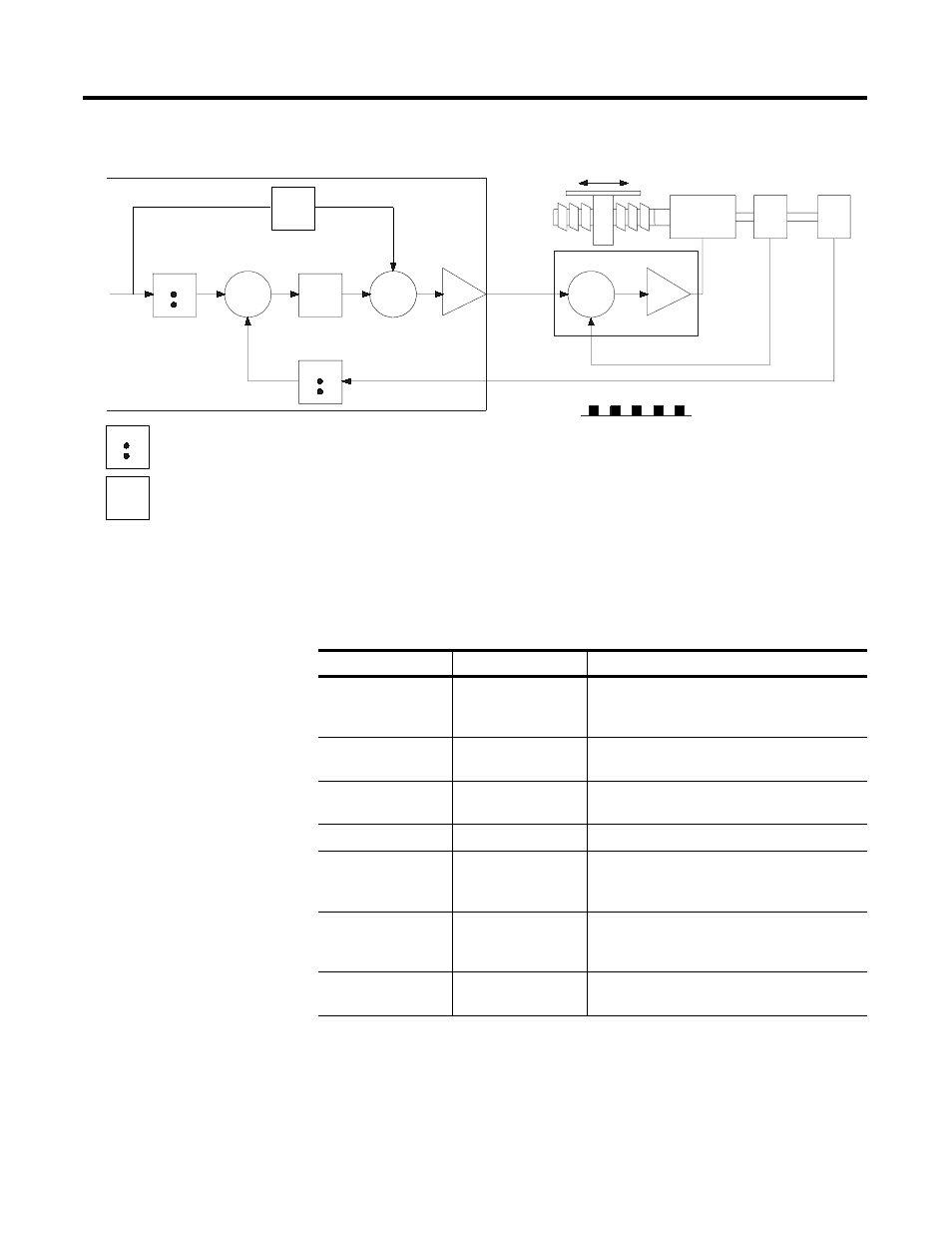
Figure 7.5 Servo Loop Parameters in a Velocity Feedforward Loop
The following table contains the name, file location, and a brief
description of the Servo Loop parameters. For more detailed
information about the parameters see Appendix A of this manual.
Control
Axis
Feedrate
Position
Command
Following
Error
Position
+
_
D/A
Velocity
Command
Velocity
Feedback
Axis Motion
Motor
Tach
Encoder
Drive Amplifier
Incremental Position Feedback
+
_
+
+
Maximum Axis Gain
Velocity and
Acceleration
Feedforward
= and amplifier
= and integrator
Name
Location
Description
DAC Enable
M0:s.0/0
Enables (provides or turns on) the DAC output
voltage or disables (turns off) DAC output by
setting the DAC output to zero.
Invert DAC
M0:s.0/1
Inverts the DAC output to change direction with
respect to the positive and negative move.
Reverse Feedback
M0:s.0/2
Reverses the sign of the incremental feedback
position acquired every servo scan.
Loop Type
M0:s.0/5, M0:s.0/4
Type of loop closure
Velocity Feedforward
Constant
M0:s.32,33
Value of the feedforward constant used for the
velocity feedforward loop closure in percentage
(0.0 to 1.0).
Acceleration
Feedforward
Constant
M0:s.34,35
Value of the feedforward constant used for the
velocity feedforward loop closure in percentage
(0.0 to 1.0).
Maximum Axis Gain
Value
M0:s.42,43
Maximum value for gain in position units per
one thousandth of position unit.