Motion parameters – Rockwell Automation 1746-HSRV SLC Servo Control Module User Manual User Manual
Page 108
Publication 1746-6.1.2 - July 2000
Setting Up Your SLC Servo Module 7-29
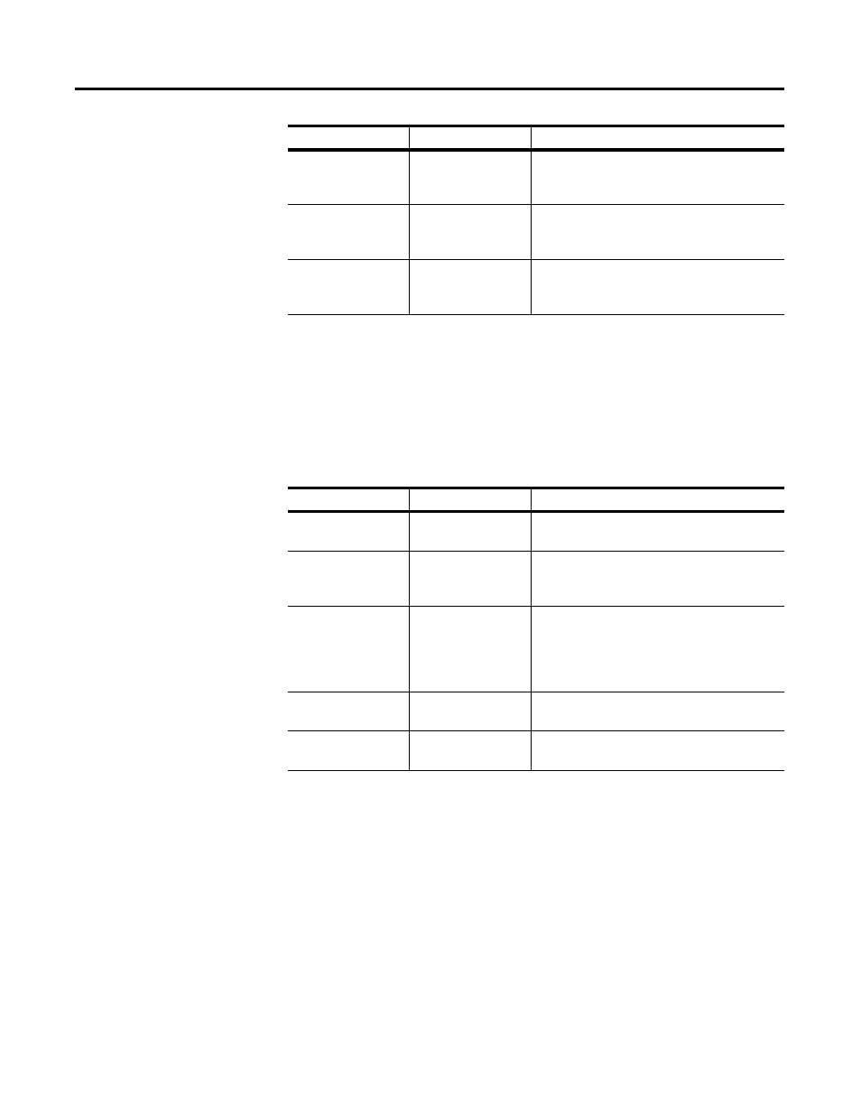
Motion Parameters
Use the motion parameters in the following table to define your
motion-related specifications (e.g., speed, time to maximum speed)
for the SLC Servo Module.
Excess Following
Error
M0:s.38,39
Value of the following error beyond which an
excess following error fault occurs in position
units.
Output Voltage at +
Max Speed
M0:s.24,25
The voltage at the DAC to command the
Maximum Axis Speed in the positive direction
in volts.
Output Voltage at –
Max Speed
M0:s.26,27
The voltage at the DAC to command the
Maximum Axis Speed in the negative direction
in volts.
Name
Location
Description
Name
Location
Description
Velocity Time Base
M0:s.0/6
Specifies the time base for the speed
parameter specification.
Synchronized Move
Source
M0:s.1/1
Specifies the source for the synchronized move
signal to be either the backplane or the
termination panel.
Maximum Axis Speed M0:s.28,29
Maximum speed for moving an axis in position
units/time unit.
Refer to the
Setting Up Your SLC Servo Module
chapter for more information
.
Time to Maximum
Axis Speed
M0:s.30,31
Maximum time to reach the maximum rated
speed for the axis in seconds.
In-position Band
M0:s.40,41
Specifies a zone around the end point for the
move within which the in-position bit gets set.