Status information, Using the set vff command, Typical set vff move data tables – Rockwell Automation 1746-HSRV SLC Servo Control Module User Manual User Manual
Page 154
Publication 1746-6.1.2 - July 2000
Programming System Variables 9-11
Using the Set VFF Command
The Set VFF command specifies the amount of position command fed
forward to reduce the amount of following error during axis motion.
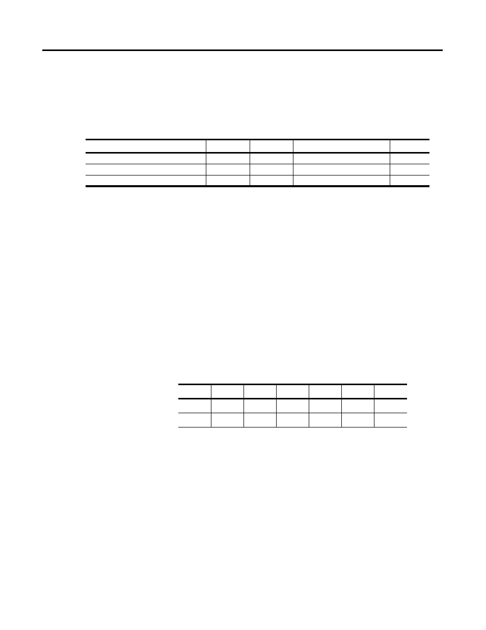
Set VFF parameters for word 5, bit 11 appear in the table below.
1
Location can vary depending on other bits simultaneously set in the most significant byte of Word 5 (up to three of
these bits can be set simultaneously). These bits are evaluated from right to left. Words 6 and 7 are used for
the first set bit encountered. Words 8 and 9 are used for the next simultaneously set bit. Words 10 and 11 are
used for the last simultaneously set bit. This special feature can be used to make servo axis tuning easier.
2
s = Slot number for the SLC Servo Module.
This online configuration command is issued anytime after the control
is powered up. Refer to the example in Using the Set Axis Gain
Command.
If the Set VFF command fails, the SLC processor is notified with an
appropriate error message.
Typical Set VFF Move Data Tables
Before executing a Set VFF move, set Source B for the Equal
instruction in Figure 9.1 to 2048. A Set VFF command to 1.0 is initiated
if the data tables are:
Status Information
Status information is described within the following topics:
•
Word 0 discrete bit status specifications
•
Series/major revision/minor revision
•
Blend move profile
•
Word 1 discrete bit status specification
•
Word 2 discrete bit status specification
•
Word 3 discrete bit status specification
Block Command Parameters
Location
1, 2
Format
Possible Values
Default
Bit Specifications
O:s.4
Bits
0000 0000 0000 0000
0
Set VFF
O:s.5
Bits
XXXX 1XXX 0000 0000
0
Velocity Feedforward Constant
O:s.6-O:s.7
Float
0.0 to 1.0
0.0
Word
0
1
2
3
4
5
F27:0
1.0
N32:0
0
0
0
0
0
2048