Rockwell Automation 1746-HSRV SLC Servo Control Module User Manual User Manual
Page 71
Publication 1746-6.1.2 - July 2000
5-28 Wiring the SLC Servo Module
because it directly affects how the 1398 is wired to the SLC Servo
Module.
Wiring the SLC Servo Module when Homing to a Marker
Both the ULTRA 100 drive (using any divisible resolution) and the
ULTRA 200 drive (using any divisible resolution) require a breakout
board (P/N 9101-1392) to interface between the integral encoder
(inside the Y, F, or H-series motor) and the SLC Servo Module
termination panel.
The breakout board allows the SLC Servo Module to read the encoder
signals directly from the encoder, instead of from the gate array circuit
inside the ULTRA 100/200. If the encoder signals are read from the
ULTRA 100/200 (using the gate arrays), the marker signal shifts with
respect to the A and B channel on each successive power cycle to the
ULTRA 100/200.
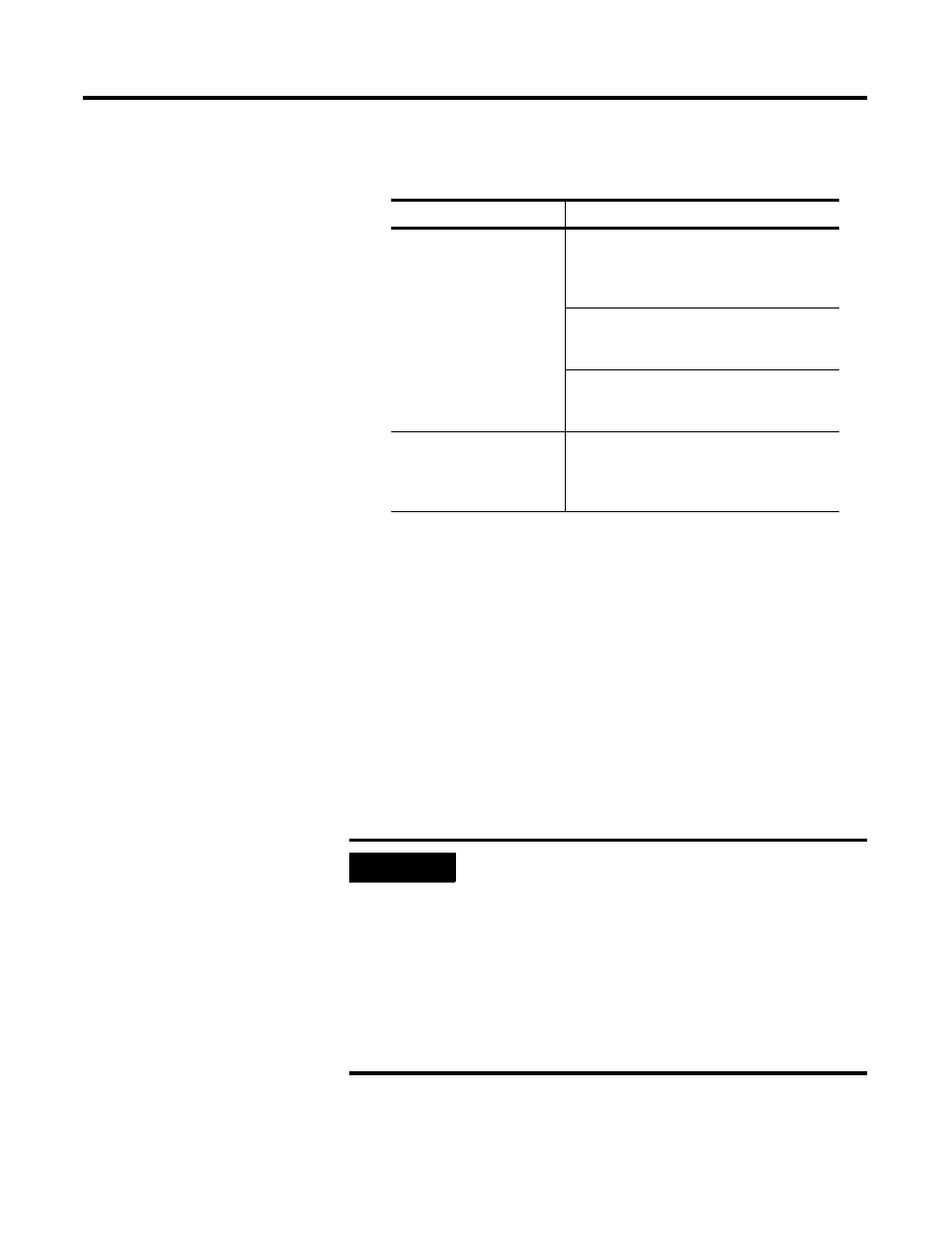
If Homing to a Marker is:
Go to:
Necessary
Figure 5.24,
Wiring Diagram for ULTRA 100
When Not Homing to a Marker and for ULTRA
200 (Manufactured After July 31, 1998) When
Homing to a Marker
Figure 5.25,
Wiring Diagram for F, H, and S
series ULTRA 100/200 (Manufactured Before
July 31, 1998) When Homing to a Marker
Figure 5.26,
Wiring Diagram for Y series
ULTRA 100/200 (Manufactured Before July 31,
1998) When Homing to a Marker
Not Necessary
Figure 5.24,
Wiring Diagram for ULTRA 100
When Not Homing to a Marker and for ULTRA
200 (Manufactured After July 31, 1998) When
Homing to a Marker
IMPORTANT
Since the ULTRA 100/200 drive can be configured to
use custom motors and custom encoders, the
guidelines stated above may not be true for other
manufacturers’ motor/encoder combinations.
ULTRA 200 drives manufactured after July 31, 1998
do not need the J2 breakout. Look for a mm/yy
date code stamped or printed on the Allen-Bradley
label, located on the side of each drive unit. For
example: Mfg. 1098 indicates the drive was
manufactured in October 1998.