Wiring the estop for system with two or more axes – Rockwell Automation 1746-HSRV SLC Servo Control Module User Manual User Manual
Page 53
Publication 1746-6.1.2 - July 2000
5-10 Wiring the SLC Servo Module
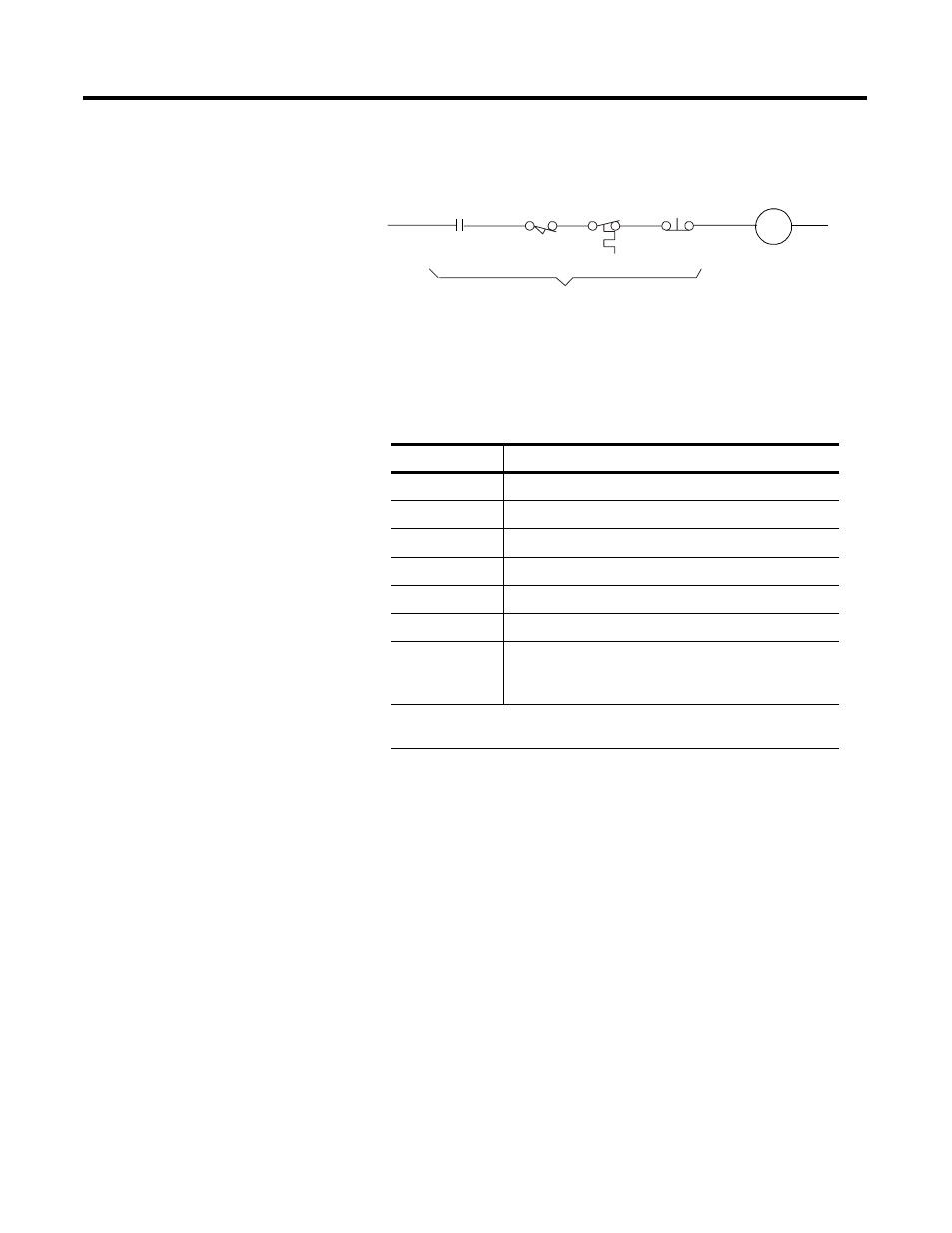
Figure 5.7 String Pilot Connection
To wire Estop connections, refer to wiring diagrams for the drive you
are using. The wiring of six different Allen-Bradley compatible drives
is shown in the table below.
Wiring the Estop for System with Two or More Axes
For a system with two or more axes, you must have a termination
panel and a SLC Servo Module for each axis. See Figure 5.8 and Figure
5.9 for the ladder diagram and Estop circuitry diagram for these
systems.
The Estop characteristics for this type of system are:
•
SLC Servo Modules must be running before the system comes
out of Estop.
•
If an axis drops into Estop, the system drops into Estop.
The power capacity of the user-supplied +24V DC power supply
determines the number of axes on one Estop string. Each Estop string
requires ~ 50 mA of current from the +24V supply.
C ustomer
E stop S tring
-
C R 2
String Pilot
Drive Fault
Contact
Overtravel
Thermal
Overload
Remote
E-Stop
Figure
Wiring Diagram
5.15
1386 DC Servo Drive
5.16
1388 DC PWM Servo Control
5.17, 5.18
1389 AC Servo Amplifier
1
5.19, 5.20
1391 AC Servo Control Module Amplifier
5.21
1392 AC Servo Amplifier
5.22, 5.22
1394 AC Servo Control Module Amplifier
5.24
5.25
5.26
1398 ULTRA 100™/200™ Series AC Servo Control
Module Amplifiers
1
The 1389 servo drive requires a 115V AC power conductor (K1) to supply main power to the
drive amplifier. See the 1389 Servo Amplifier Installation Manual for details