Rockwell Automation 1746-HSRV SLC Servo Control Module User Manual User Manual
Page 70
Publication 1746-6.1.2 - July 2000
Wiring the SLC Servo Module 5-27
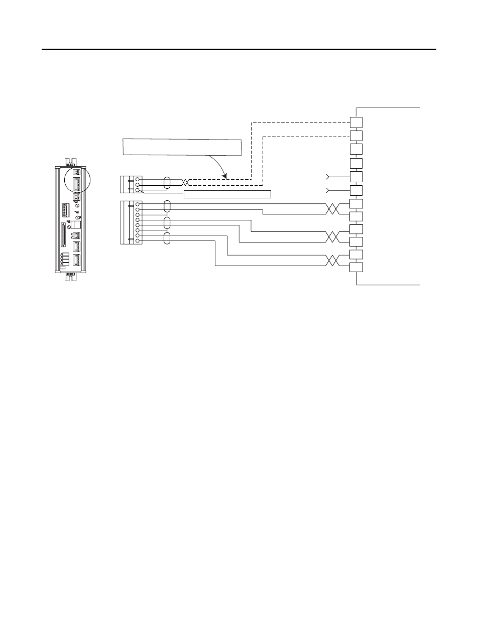
Figure 5.23 Wiring Diagram for 1394 Systems (continued)
To perform a 1394 auto-tune function, the 1394 must be enabled prior
to initiating the auto-tune command. However, if the SLC Servo
Module is not out of Estop, the M1 coil will not energize and the A0
Enable signal will not be present.
If it is necessary to auto-tune the 1394 drive prior to the SLC Servo
Module coming out of Estop, do the following:
•
Place a temporary jumper between TB2-17 and the Stop PB to
allow the M1 coil to energize.
•
Apply a 24V DC signal to the A0 Enable input on the 1394 to
execute the auto-tune command.
Wiring the SLC Servo Module to 1398 ULTRA 100/200
When wiring the SLC Servo Module to an ULTRA 100/200 drive,
consider beforehand if homing to an encoder marker is necessary
1
7
2
8
3
9
D R IV E
D R IV E
D R R E T
S H L D
CHANNEL A HIGH
CHANNEL A LOW
CHANNEL B HIGH
CHANNEL B LOW
CHANNEL Z HIGH
CHANNEL Z LOW
Bulletin 1394
E N C O D E R
C H A . H I
C H A . L O
A B S H L D
C H B . H I
C H B . L O
Z S H L D
C H Z . H I
C H Z . L O
AQB Board
4
10
5
11
6
12
Axis x Vref +
Axis x Tref-
Axis x Vref-
+5V DC Power Supply
Axis x Tref+
Power Supply Common
User Supplied
User Supplied
Important:
Connect only if Vref is not used
on the input wiring board.
Connect this to the PE of the 1394