Rockwell Automation 1715-OF8I Redundant I/O System User Manual User Manual
Page 88
88
Rockwell Automation Publication 1715-UM001C-EN-P - March 2014
Chapter 2
Installation Instructions
1715-OB8DE Digital Output Module Functional Block Diagram
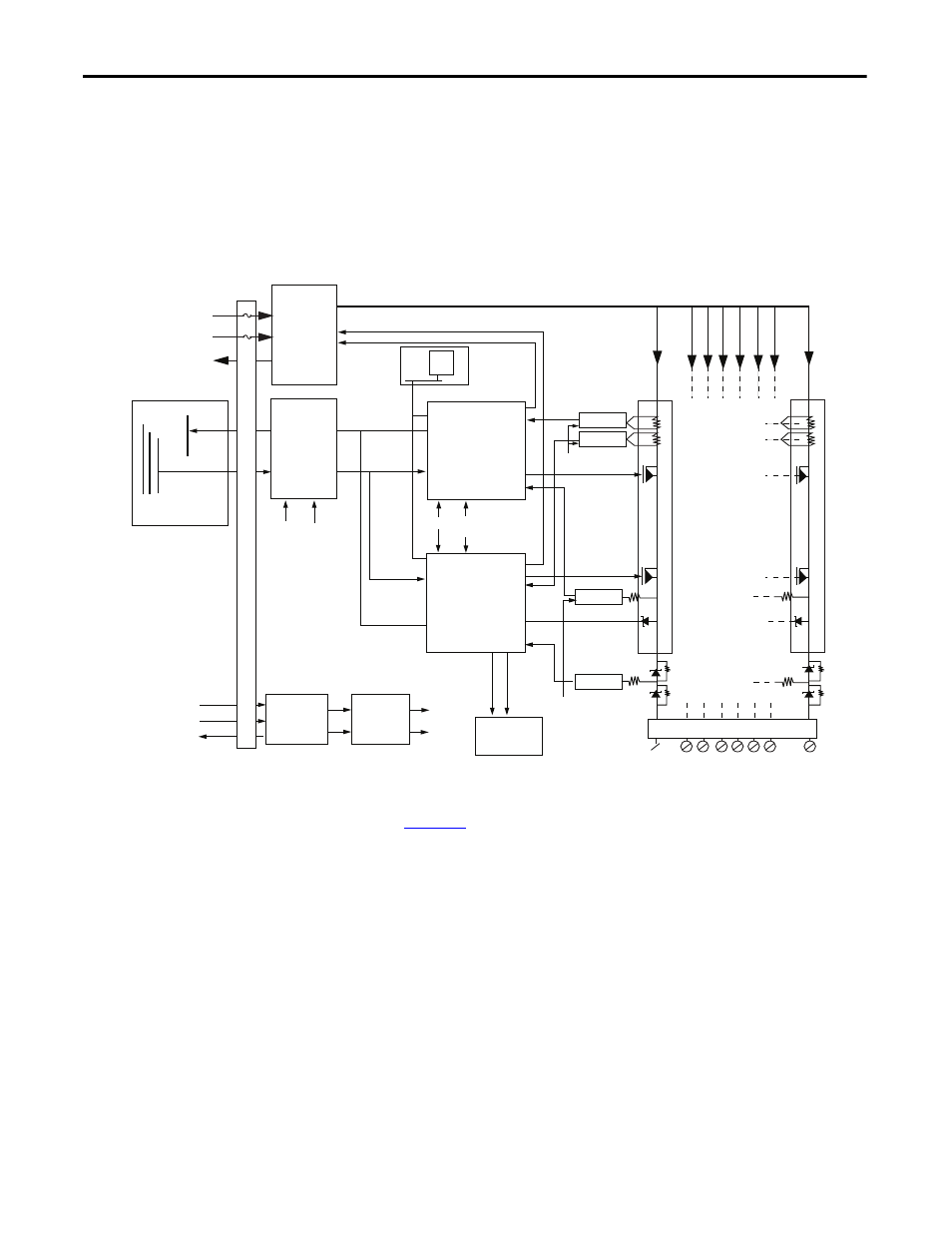
Figure 37 - 1715-OB8DE Functional Bock Diagram
. The field output channel is controlled by two independent
output switch control units. The field output circuitry is galvanically isolated
from the processor input commands and response lines by an isolated interface
circuit. This architecture protects the system processors from faults in the
module’s output control circuits and possible field device faults.
Module power is produced by the internal isolated power supply, supplied by the
dual redundant system power inputs. Over- and under-voltage protection is
applied to the module internal power supply outputs.
VFIELD 1
VFIELD 2
Response Bus
24V
FIELD
POWER
Response
Command A,B,C
I/0 Command Bus
I/0 Backplane
VFIELD
OV RTN
Power
Combiner
Isolated
Backplane
Interface
PWR Power
Valid
PWR Power
Valid
Response
Command
Command
Dual
Redundant
System
Power
SYS_24V1
SYS_24V2
SYS_OV
Isolated
Power
Supply
Over/Under
Voltage
Protection
PWR
Power
Valid
LED Array
Front Panel
Channel
Status
Module
Status
VREF
Termination
Assembly
CH0
CH7
Transient
Suppression
VMON B
VMON A
Output Control
Output Control
Reverse Voltage
Blocking
IMON B
IMON A
VREF
Data Management
& Output Switch
Control A
PWR Feed Combiner Drives
SPI
Flash
Response
Combined Power Feed
Termination
Assembly
Data Management
& Output Switch
Control B
32107-M1