Reaction times, System reaction time – Rockwell Automation 1715-OF8I Redundant I/O System User Manual User Manual
Page 219
Rockwell Automation Publication 1715-UM001C-EN-P - March 2014
219
1715 Redundant I/O System in SIL 2 Safety Applications
Chapter 6
Reaction Times
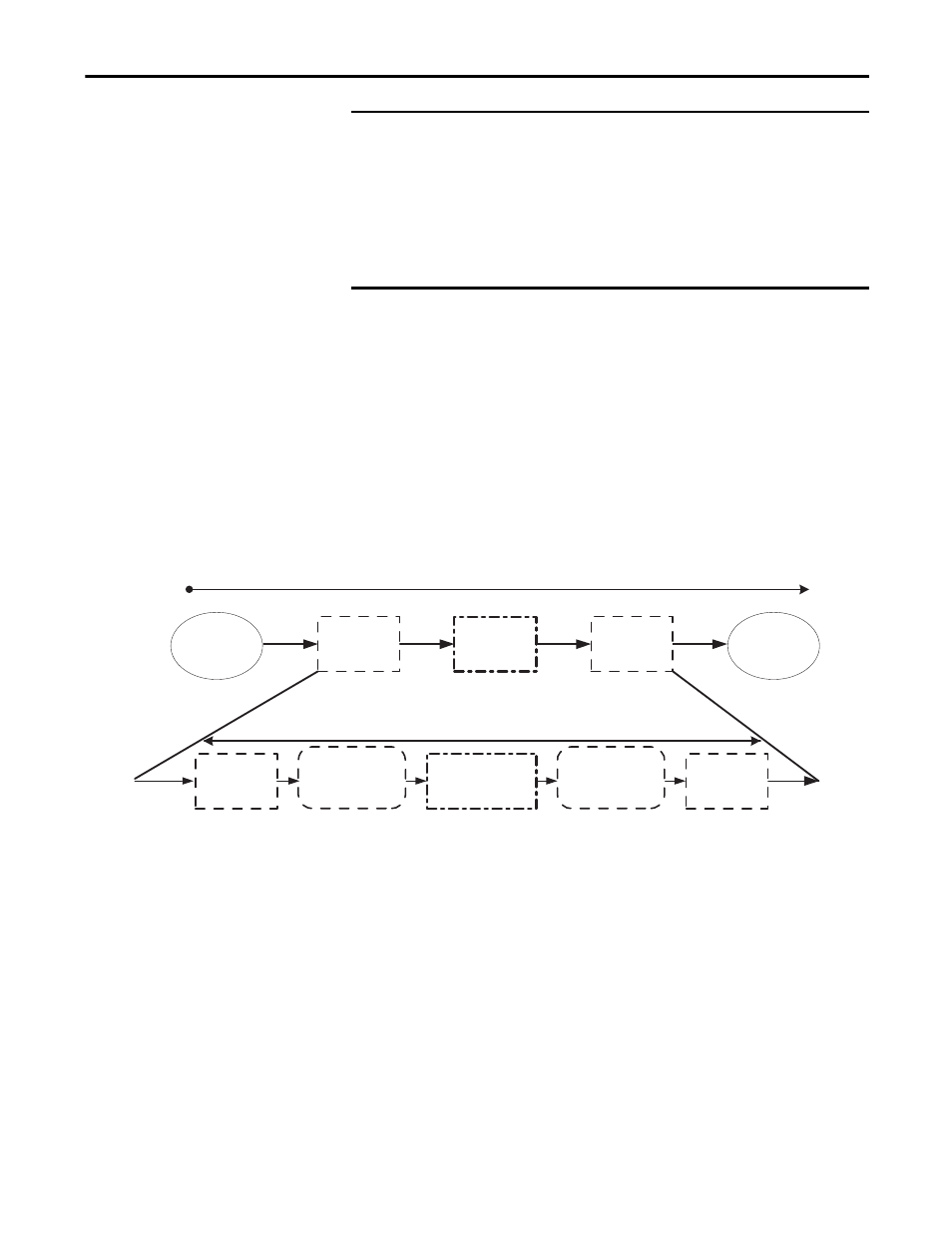
To determine the system reaction time of any control chain, you must add up the
reaction times of all of components of the safety chain.
System Reaction Time
System Reaction Time = Sensor Reaction Time + Logix System Reaction Time
+ Actuator Reaction Time
Figure 63 - System Reaction Time
IMPORTANT The Reset Counters button on the diagnostics tab resets only the counters shown
in the 1715 I/O module profiles.
It does not reset the counters displayed within the ControlLogix Add-On
Instructions.
This diagnostic information is populated by values retrieved from 1715 output
modules. Equivalent input module diagnostic data is made available by the
Add-On Instructions.
System Reaction Time
Sensor Reaction
Time
Input Reaction
Time
Safety Task
Reaction Time
Output Reaction
Time
Actuator
Reaction Time
Input Module
Delay
Input Connection
Reaction Time Limit
Safety Task Period
+
Safety Task Watchdog
Output Connection
Reaction Time Limit
Output Module
Delay