Rockwell Automation 1715-OF8I Redundant I/O System User Manual User Manual
Page 65
Rockwell Automation Publication 1715-UM001C-EN-P - March 2014
65
Installation Instructions
Chapter 2
connections for three I/O termination assemblies and three I/O modules. The
locations for each I/O termination assembly and I/O module connectors are
paired, and together represent an I/O module slot.
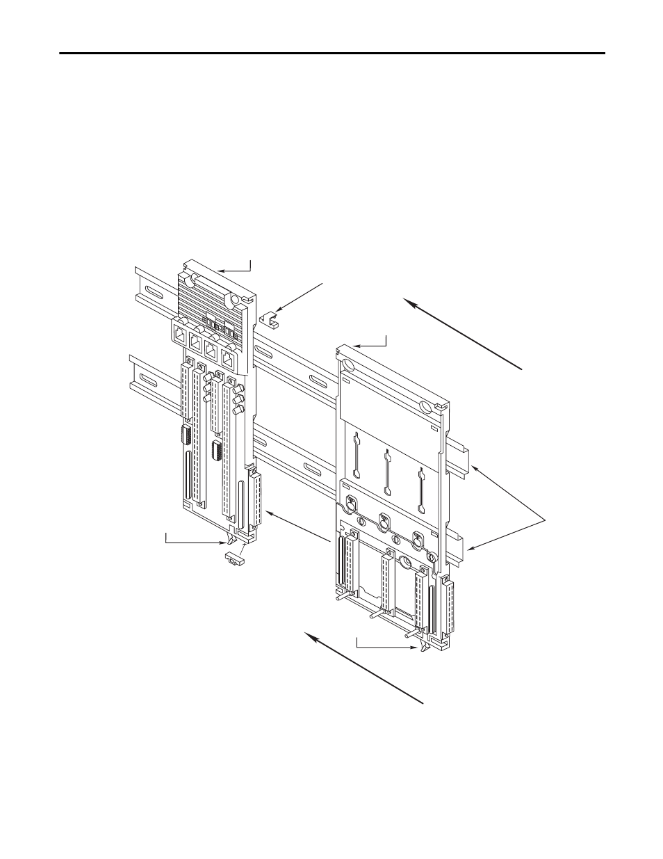
To mount the 1715-A3IO base unit, follow these steps.
1. Mount each 1715-A3IO base unit onto the DIN rails to the right of the
1715-A2A adapter base unit.
2. Slide the base unit to the left until the joining connectors are fully mated.
3. Secure the I/O base unit onto the DIN rails by sliding the bottom
retaining lever (below the base unit) as far to the left as it goes until it
latches in the locked position.
4. Insert the retaining clips into the top and the bottom slots to connect the
adapter base unit to the I/O base unit.
Adapter Base Unit
I/O Base Unit
Retaining Clip
Retaining Clip
DIN Rails
Retaining Lever
Mating
Connector
Retaining Lever
45247