Layout the hardware, System context – Rockwell Automation 1715-OF8I Redundant I/O System User Manual User Manual
Page 20
20
Rockwell Automation Publication 1715-UM001C-EN-P - March 2014
Chapter 1
Redundancy System Overview
Layout the Hardware
This section discusses how to layout the system’s hardware by topology.
System Context
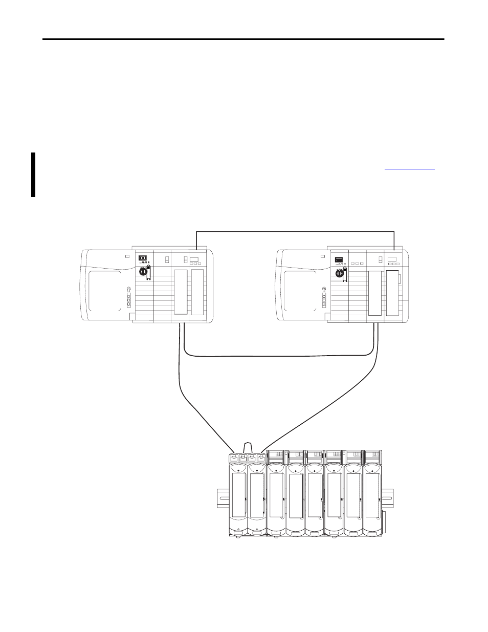
The redundant I/O subsystem must be connected to one ControlLogix
redundancy system, or any Logix system that supports I/O via the
EtherNet/IP network. All connections are established via the Ethernet network
by using the topologies supported by the 1756-EN2T or 1756-EN2TR module,
that is, DLR (Ring) or Star.
For additional information about DLR topologies, see the EtherNet/IP
Embedded Switch Technology Application Guide, publicatio
Figure 2 - 1715 Redundant I/O System DLR (ring) Topology Attached to a 1756 ControlLogix
Enhanced Redundancy System
1756-RM2
1756-EN2TR
IO BASE
1715-A310
CH1
CH1
CH1
CH1
CH1
CH1
CH1
CH1
TERMINAL IDENTITY
AOTA
Dual.
CH1
CH1
CH1
CH1
CH1
CH1
CH1
CH1
TERMINAL IDENTITY
AOTA
Dual.
CH1
CH1
CH1
CH1
CH1
CH1
CH1
CH1
TERMINAL IDENTITY
AOTA
Dual.
IO BASE
1715-A310
CH1
CH1
CH1
CH1
CH1
CH1
CH1
CH1
TERMINAL IDENTITY
AOTA
Dual.
CH1
CH1
CH1
CH1
CH1
CH1
CH1
CH1
TERMINAL IDENTITY
AOTA
Dual.
CH1
CH1
CH1
CH1
CH1
CH1
CH1
CH1
TERMINAL IDENTITY
AOTA
Dual.
1715-AENTR
1756-EN2TR
1756-RM2
1715-AENTR
1715-I/O
1715-I/O
1715-I/O
1715-I/O
1715-I/O
1715-I/O
1756 ControlLogix
Primary Chassis
1756 ControlLogix
Secondary Chassis
1756 RM Cable
1715 Redundant I/O
System
45242