Rockwell Automation 198x Modular DeviceNet Starter Auxiliary I/O User Manual
Page 42
3-22
Publication 198-UM001B-EN-P September 2001
EXAMPLE
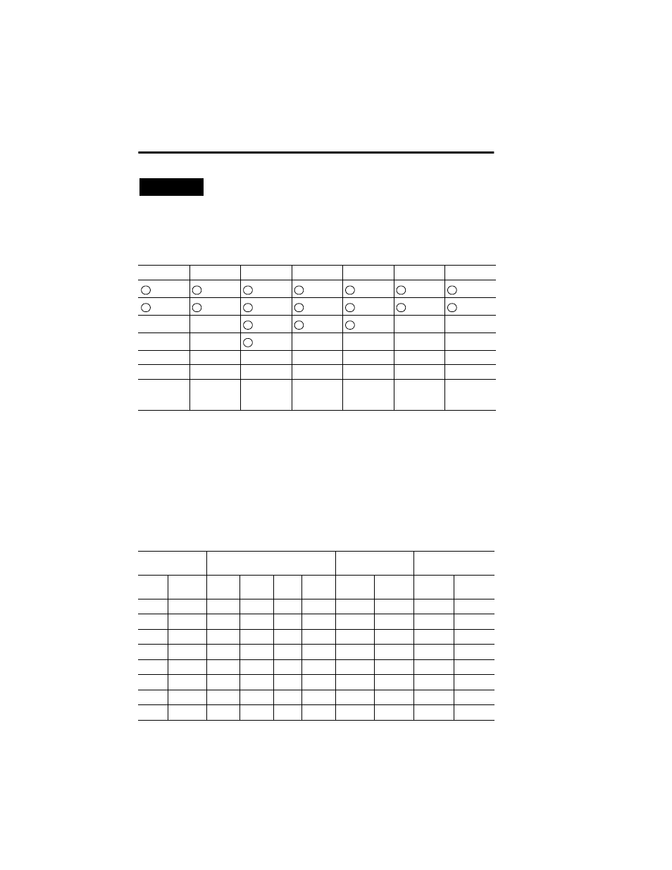
Figure 3.1 Lineup
In the above example you can see that the first module from the left is the DeviceNet
Module. The DeviceNet Module doesn’t have any instances. The next module is Mod1. It
contains the first output (Out 1) and second output (Out2), which are recognized as
output instance 1 and output instance 2, respectively. Input In1 on Mod2 is the first input
seen from the left, therefore it becomes input instance 1. Similarly In2 of Mod3 is the sixth
input seen from the left, therefore it becomes input instance 6. The other instances in this
system is done in a similar fashion and can be found in the table below, followed by a blank
table for you to record your line-up.
Mod 0
Mod 1
Mod 2
Mod 3
Mod 4
Mod 5
Mod 6
Mod/Net
Out 1
In 1
In 1
In 1
In 1
In 1
I/O
Out 2
In 2
In 2
In 2
In 2
In 2
In 3
Out 1
Out 1
In 4
Cat. No.
198-DN
Cat. No.
198-OW2
Cat. No.
198-IB4
Cat. Nos.
198-IA2X,
198-OW1
Cat. Nos.
198-IB2X,
198-OB1
Cat. Nos.
198-IA2
Cat. No.
198-IB2S
Table 3.D Instance Table
Module
Description
Input Instances
Output Instances
Presence Sensing
Instances
Mod.
Slot
Mod.
Type
In 1
In 2
In 3
In 4
Out 1
Out 2
Sensor 1
(In 1)
Sensor 2
(In 2)
0
DNet
—
—
—
—
—
—
—
—
1
2 Output
—
—
—
—
1
2
—
—
2
4 DC Input 1
2
3
4
—
—
—
—
3
AC Starter 5
6
—
—
3
—
—
—
4
DC Starter 7
8
—
—
4
—
—
—
5
2 AC Input 9
10
—
—
—
—
—
—
6
Sensor
—
—
—
—
—
—
1
2
7…16
Module
—
—
—
—
—
—
—
—