MacDon M100 SP Operators Manual User Manual
Page 64
OPERATOR’S STATION
169304
62
Rev. C
2. Release the safety lock on the header lift
cylinders.
3. Lower header down onto the transport
wheels.
4. Disengage the top link from the header.
Use the header tilt switch to release load on
the cylinder if necessary.
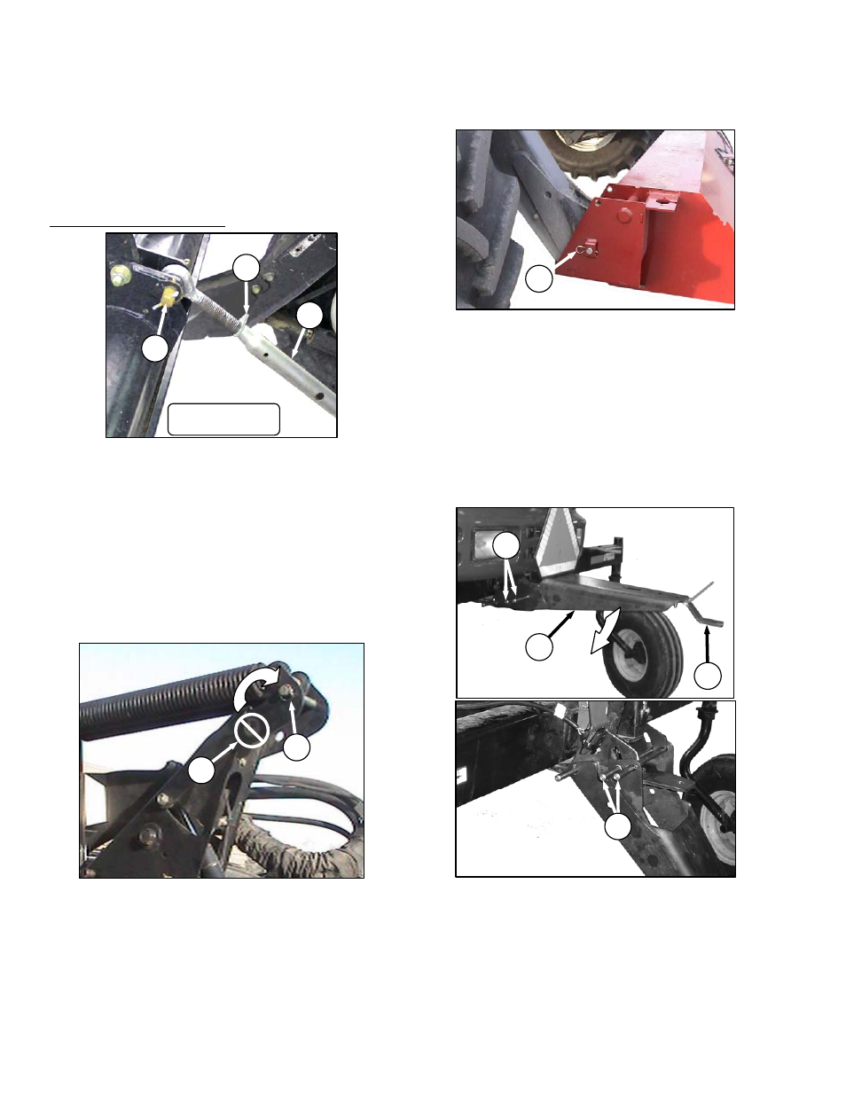
MECHANICAL LINK – M150
1. Loosen nut (G) and rotate barrel (H) to
relieve load on link.
2. Remove cotter pin on pin (J), and remove
pin to disconnect from windrower. Re-install
pin in header.
i.
Back windrower away from header.
j.
Remove tow-bar sections from storage locations
on header, assemble, and attach to header.
See Header Operator’s Manual.
6.3.8.2.1.2 Attach Weight Box To Windrower.
IMPORTANT
To prevent damage to the lift system when
lowering header lift linkages without a
header or weight box attached to
windrower, ensure that float engagement
pin is installed in storage location (C), and
not installed at hole location (B).
a. Drive windrower so that windrower lift arms are
positioned into the weight box pockets.
b. Raise lift arms slightly.
c. Stop engine and remove key.
d. Install locking pins (D) into pockets and thru
windrower header lift linkages. Secure with
hairpin.
NOTE
Pins (D) were previously removed from
the header lift linkage lower end.
e. At rear of windrower, lower the drawbar bracket
from field position as follows:
1. Hold drawbar support (K) and remove the
two pins (L) at the forward end.
2. Lower support to position shown and re-
install the two pins in uppermost pair of
holes in support.
3. Alternate drawbar (M) can be removed if
desired.
J
H
G
D60 SHOWN
D
B
C
G
K
L
M