MacDon M100 SP Operators Manual User Manual
Page 113
MAINTENANCE/SERVICE
169304
111
Rev. C
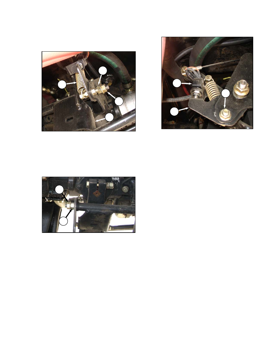
57.5.3.5 Neutral Lock Structure
a. Check for proper movement of interlock support
structure as follows:
1. Disconnect spring (A) to unload pivots.
2. Check that support (B) rotates freely and
that there is no fore-aft movement of
structure.
3. If no adjustment is required, reconnect
spring (A).
b. If necessary, adjust as follows:
1. Loosen outer nut (C).
2. Turn inner nut (D) until washer just contacts
the plastic bushing. This pivot must allow
free rotation of the support structure.
3. Hold inner nut (D) with a wrench and tighten
outer nut (C) against nut (D).
4. Loosen outer nut (E).
5. Turn inner nut (F) until washer contacts the
front support. Check again for free rotation
of the structure with no fore-aft movement.
6. Hold inner nut (F) with a wrench and tighten
outer nut (E) against inner nut (F).
7. Torque outer nuts (C) & (E) to 60-70 ft·lbf
(80-90 Nm).
8. Reconnect spring (A).
57.5.3.6 Neutral Start Switch
The neutral start switch (G) must be closed
before the engine can be started. The switch is
closed when the neutral interlock on the pump is
activated by positioning the GSL into N-DETENT
and locking the steering wheel in centre position.
When the switch closes, and machine starts and
runs, the brakes continue to be applied to the
drive wheels as park brake solenoid 3 is
energized preventing brake release. The neutral
switch is located on the frame adjacent to the
hydrostatic transmission.
a. Check that electrical connections are good at
neutral start switch (G).
b. Check that the plunger of switch is fully
compressed when the steering is locked and the
GSL is fully in N-DETENT. Adjust switch
support if required as follows:
1. Loosen nut (H) and adjust support (J) as
required.
2. Tighten nut (H).
IMPORTANT
Do not over-adjust switch support, as this
will prevent pintle arms from locking.
D
C
A
B
F
E
G
H
J