Electrical isolation, Device protection, Electrical installation – Lenze i700 Manual User Manual
Page 85
Electrical installation
Important notes
Electrical isolation
l
85
EDS700ACBA EN 4.0
6.1.1
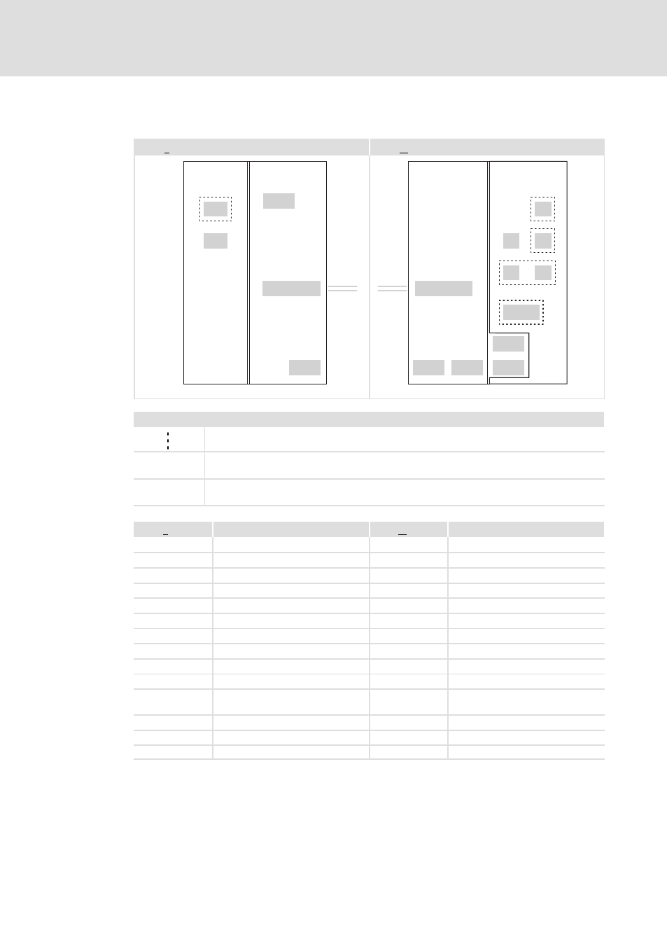
Electrical isolation
E70ACP...
E70ACM...
X20
X21
X101/102
X103
X100
X1
X2
X3
X4
X5
X7/X8
X101/102
X105
X106
X107
X108
i700A00x
Legend
Isolation by functional insulation
I
Isolation by basic insulation
II
Safe isolation by double or reinforced insulation
Protection against accidental contact is guaranteed without any further measures.
E70ACP...
Power supply module
E70ACM...
Axis module
Power section
Power section
Control section
Control section
X1
Safety system
X20
Digital inputs and outputs
X2
Digital inputs
X21
24−V voltage supply
X3
24−V voltage supply
X100
AC mains
X101/102
DC bus +UG/−UG
X101/102
DC bus +UG/−UG
X103
Brake resistor
X4/X5
EtherCAT
X7/X8
Resolver or encoder
X105
24−V voltage supply of motor
holding brake
X106
Motor holding brake
X107
Motor B
X108
Motor A
6.1.2
Device protection
The trouble−free operation of power supply modules with an external brake resistor is only
ensured if an axis module is installed in the immediate vicinity. Preferably by end−to−end
mounting and use of the DC busbar system (X101/X102).