Technical data, Rated data supply modules – Lenze i700 Manual User Manual
Page 34
Technical data
Rated data
Supply modules
l
34
EDS700ACBA EN 4.0
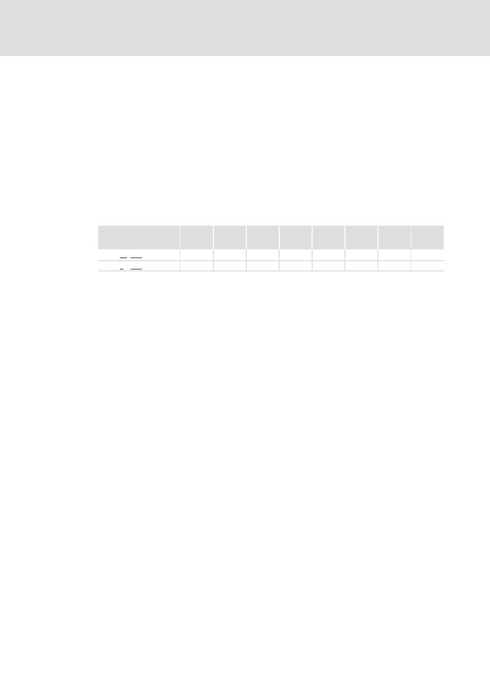
Rated data for internal brake chopper
To be able to dissipate the excess energy produced during operation in generator mode,
the power supply modules are equipped with an internal brake chopper/brake transistor.
For this purpose, an external brake resistor corresponding with the technical data from the
optional accessories must be connected to X103.
If the DC−bus voltage exceeds 765 V, the brake chopper connects the external brake
resistor.
In order to increase the braking power, several power supply modules with a brake chopper
and a brake resistor can be used in parallel. Additional information can be obtained from
page 119.
RBmin
[
W]
I
BRmax
[A]
P
BRmax
[kW]
I
BRd
[A]
P
Bd
[kW]
t
Z
[s]
t
on
[s]
t
fp
[s]
Type
E70ACPSx0304x
18
42.5
32.5
16.7
5.0
97
15
15
E70ACPSx0604x
9
85.0
65.5
33.4
10.1
97
15
15
R
Bmin
Minimum brake resistance, nominal value ±10 %
I
BRmax
Peak current
P
BRmax
Peak braking power
I
BRd
Continuous current RMS − important for the dimensioning of the cables
P
Bd
Continuous braking power
t
Z
Cycle time, periodic load change with running time and recovery time
t
on
Running time
t
Z
− t
on
Recovery time
t
fp
Maximum running time without initial load and compliance with the recovery
time
The trouble−free operation of power supply modules with an external brake resistor is only
ensured if an axis module is installed in the immediate vicinity. Preferably by end−to−end
mounting and use of the DC busbar system (X101/X102).