Electrical installation, 8 electrical installation, Safety engineering – Lenze i700 Manual User Manual
Page 135
Safety engineering
Electrical installation
l
135
EDS700ACBA EN 4.0
10.7
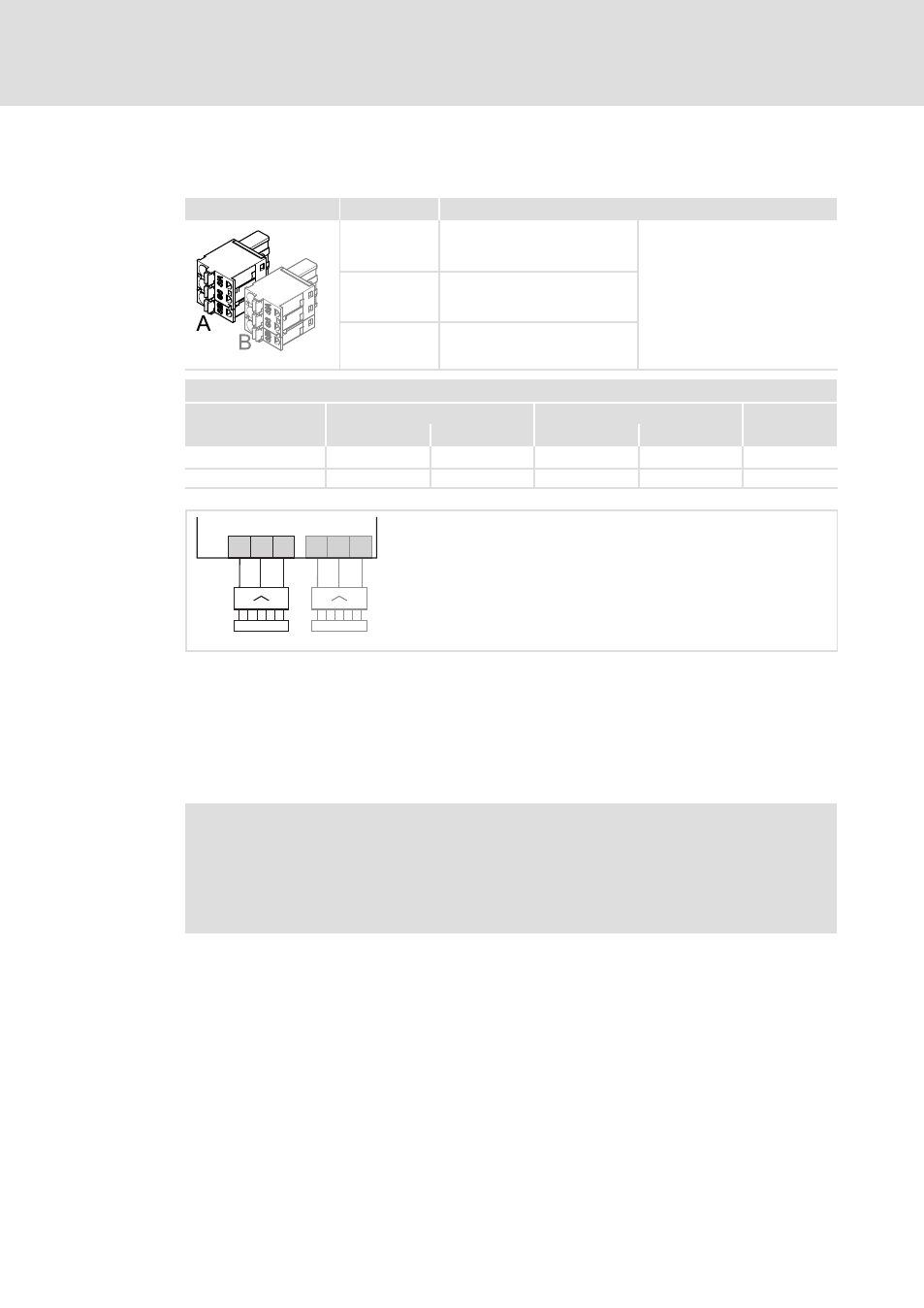
Electrical installation
X1
Labelling
Description
SIA
Safe input, channel A
On double axis devices, there are
two of these connections. For the
assignment to the axes, the
designations "A" / "B" are used.
Independently of this, the
two−channel safe input is always
provided with the channels A
and B.
GS
Reference potential GND
SIB
Safe input, channel B
i700P00x
Terminal data
Conductor cross−section
Tightening torque
!
[mm
2
]
[AWG]
[Nm]
[lb−in]
flexible
0.2 ... 2.5
24 ... 12
−
−
3.5 x 0.6
Rigid
0.2 ... 2.5
24 ... 12
−
−
3.5 x 0.6
SIB
GS
SIA
B
SIB
GS
SIA
A
X1
i700M00x
Fig. 14
Wiring of X1
X1
Connection of integrated safety system
A
1−axis module
B
Additionally for 2−axis module
SIA
Safety system input, channel A
SIB
Safety system input, channel B
GS
Reference potential GND
)
Note!
To avoid interchanging of the plug−in terminals − especially in the case of
double axis devices −, the plug−in terminals can be provided with coding pins.
Alternatively, we recommend to label the terminals clearly in order to enable
the correct assignment of plugs and sockets.