Technical data, Ab c d e – Lenze i700 Manual User Manual
Page 63
Technical data
Terminal description
Axis modules
l
63
EDS700ACBA EN 4.0
1
0
2
3
a
b
c
d
e
U
V
W
BD1
(T1)
BD2
(T2)
PE
i700MOTL1
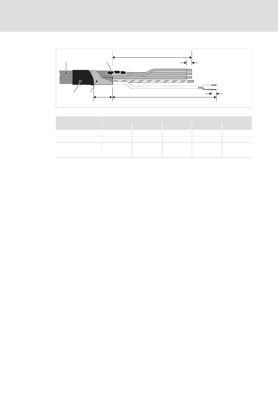
Fig. 4−4
Stripping lengths of the motor cable
[mm]
a
b
c
d
e
E70ACMSxxxx4xx1xxx
180
8
40
210
8
E70ACMSxxxx4xx2xxx
180
8
40
210
8
E70ACMSx0324xx1xxx
E70ACMSx0484xx1xxx
E70ACMSx0644xx1xxx
180
8
40
210
8
How to proceed:
1. Strip motor cable
0 as specified.
2. Fold back the shield of the motor cable
1 over the cable sheath.
3. Stabilise the shield with self−adhesive conductive foil
2 (recommendation).
4. Fix the shield and conductive foil with heat−shrinkable tube
3 on the cable sheath.
5. The terminals are directly suitable for the utilisation of flexible conductors. Short
circuits between the terminal connections are ruled out by the design if the
specified stripping length is met.
– Wire end ferrules can be used.
– If insulated wire end ferrules are used, it must be ensured that the effective
clamping length is not reduced by the plastic collar.
6. Apply the shields separately on the shield sheet using shield clamps (no strain relief).
- p300 Mounting Instructions (12 pages)
- p300 Operating Instructions (37 pages)
- I/O system 1000 System Manual (744 pages)
- CS5800 Mounting Instructions (89 pages)
- CS5800 Operating Instructions (60 pages)
- Controller-based Automation (63 pages)
- Controller-based Automation (68 pages)
- 2121IB LECOM-Li (29 pages)
- HMI for visualisation / with control technology (96 pages)
- Controller 3200 C Operating Instructions (40 pages)
- c300 Operating Instructions (35 pages)
- EL 1800 Mounting Instructions (89 pages)
- EL 1800 Operating Instructions (57 pages)
- 3200 C (38 pages)
- 3200 C (195 pages)
- CPC 2800 Mounting Instructions (59 pages)
- CPC 2800 Operating Instructions (39 pages)
- CS 5000 DVI Mounting Instructions (86 pages)
- CS 5000 DVI Operating Instructions (53 pages)
- MP 800 DVI Mounting Instructions (88 pages)
- MP 800 Operating Instructions (43 pages)
- 8400 protec Manual (198 pages)
- 8400 motec Manual (121 pages)
- 8400 motec Mounting Instructions (164 pages)
- 9400 Manual (584 pages)
- 9400 Mounting Instructions (208 pages)
- 8400 (304 pages)
- 8400 (1494 pages)
- 8400 BaseLine Manual (114 pages)
- 8400 BaseLine Guide Quick Guide (10 pages)
- EZAEDE1000 (76 pages)
- EMF2180IB EthernetCAN (134 pages)
- EMF2181IB (154 pages)
- EMF2181IB (83 pages)
- EMF2177IB (28 pages)
- EMF2177IB (18 pages)
- E84AZESR RFI filter 3-29A (154 pages)
- E84AZESM Mains filter-RFI filter 42-96A (120 pages)
- ESVZAR0 RS-485 (33 pages)
- ESV SMV frequency inverter (66 pages)
- CANopen Controller-based Automation (110 pages)
- PROFIBUS Controller-based Automation (55 pages)
- EtherCAT Controller-based Automation (205 pages)
- PROFINET Controller-based Automation (44 pages)