Technical data, Terminal description axis modules, Encoder – Lenze i700 Manual User Manual
Page 57
Technical data
Terminal description
Axis modules
l
57
EDS700ACBA EN 4.0
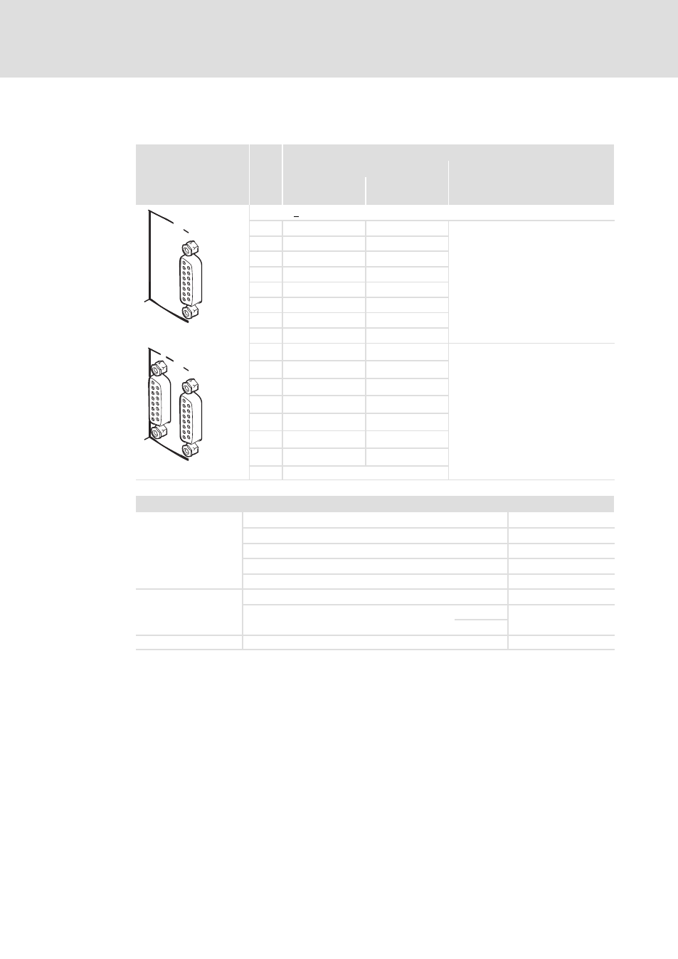
Encoder
X8
Pin
Description
EYF001... cable
1 V
SS
1 V
SS
Hiperface
X8
E70ACM...E
1
A
COS
On single axis devices, this
connection is located on the
right−hand side below the labelling
"X8".
2
GND
GND
3
B
Sin
4
V
CC
V
CC
5
Z
+RS485
6
n. c.
n. c.
7
−KTY
−KTY
8
n. c.
n. c.
B
A
X8
9
/A
Ref COS
On double axis devices, there are two
of these connections. For the
assignment to the axes, the
designations "A" / "B" are used.
10
n. c.
n. c.
11
/B
Ref SIN
12
n. c.
n. c.
13
/Z
−RS485
14
+KTY
+KTY
15
n. c.
n. c.
i700AX007 a b
"
Shield connection at Sub−D housing
Electrical data
General
Cable length (system cable is recommended)
Max. 50 m
Encoder types
Sin/cos encoder, 1V
SS
Protocols
Hiperface®
Number of increments
1 ... 16383
Input frequency
max. 250 kHz
VCC
(GND)
Supply voltage
5 V ... 12 V
Current, max.
9 V
250 mA
12 V
+KTY, −KTY
Type
KTY 83−110
- p300 Mounting Instructions (12 pages)
- p300 Operating Instructions (37 pages)
- I/O system 1000 System Manual (744 pages)
- CS5800 Mounting Instructions (89 pages)
- CS5800 Operating Instructions (60 pages)
- Controller-based Automation (63 pages)
- Controller-based Automation (68 pages)
- 2121IB LECOM-Li (29 pages)
- HMI for visualisation / with control technology (96 pages)
- Controller 3200 C Operating Instructions (40 pages)
- c300 Operating Instructions (35 pages)
- EL 1800 Mounting Instructions (89 pages)
- EL 1800 Operating Instructions (57 pages)
- 3200 C (38 pages)
- 3200 C (195 pages)
- CPC 2800 Mounting Instructions (59 pages)
- CPC 2800 Operating Instructions (39 pages)
- CS 5000 DVI Mounting Instructions (86 pages)
- CS 5000 DVI Operating Instructions (53 pages)
- MP 800 DVI Mounting Instructions (88 pages)
- MP 800 Operating Instructions (43 pages)
- 8400 protec Manual (198 pages)
- 8400 motec Manual (121 pages)
- 8400 motec Mounting Instructions (164 pages)
- 9400 Manual (584 pages)
- 9400 Mounting Instructions (208 pages)
- 8400 (1494 pages)
- 8400 (304 pages)
- 8400 BaseLine Manual (114 pages)
- 8400 BaseLine Guide Quick Guide (10 pages)
- EZAEDE1000 (76 pages)
- EMF2180IB EthernetCAN (134 pages)
- EMF2181IB (83 pages)
- EMF2181IB (154 pages)
- EMF2177IB (28 pages)
- EMF2177IB (18 pages)
- E84AZESR RFI filter 3-29A (154 pages)
- E84AZESM Mains filter-RFI filter 42-96A (120 pages)
- ESVZAR0 RS-485 (33 pages)
- ESV SMV frequency inverter (66 pages)
- CANopen Controller-based Automation (110 pages)
- PROFIBUS Controller-based Automation (55 pages)
- EtherCAT Controller-based Automation (205 pages)
- PROFINET Controller-based Automation (44 pages)