Busbar system for the dc bus, Technical data – Lenze i700 Manual User Manual
Page 31
Technical data
Rated data
Busbar system for the DC bus
l
31
EDS700ACBA EN 4.0
4.2.2
Busbar system for the DC bus
The DC busbar system of the i700 device series is dimensioned for 100 A effective current
(RMS). It responds to the arising thermal load with a time constant of approximately 5
minutes.
Using an upstream mains choke or mains filter (integrated mains choke) reduces the
harmonic content of the mains current and the DC bus current. Hence, the permissible
supply power P
DC
is increased at 100 A RMS.
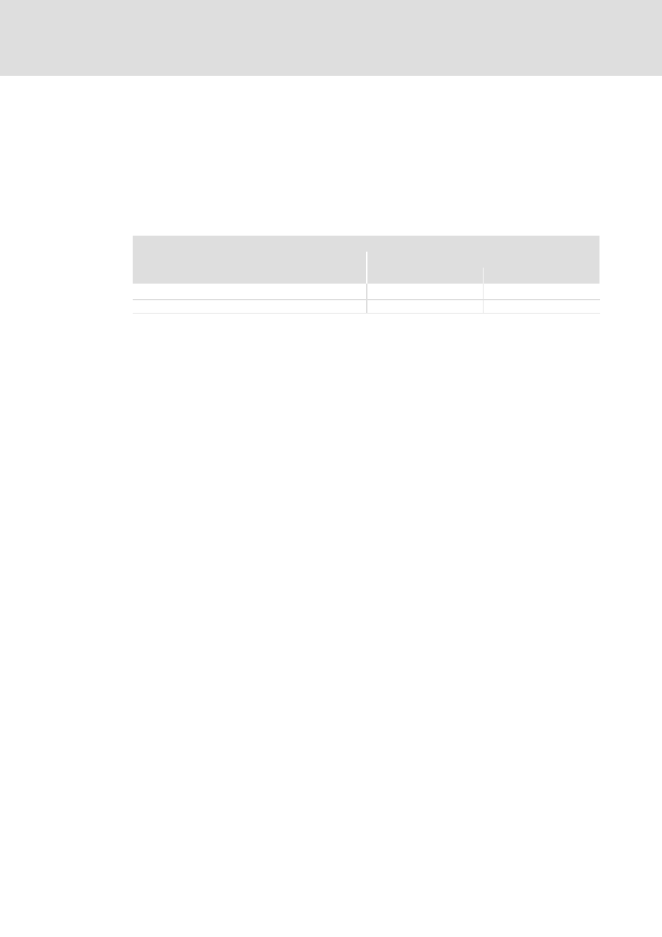
Permissible supply power P
DC
(via the DC busbar system)
Mains voltage
400 V
480 V
i700 power supply module with mains choke/filter
£ 51 kW
£ 62 kW
i700 power supply module without mains choke/filter
£ 34 kW
£ 41 kW
The required supply power P
DC
consists of the sum of the power requirement of the single
controllers (see also from page 113).
In many cases, the rated power of the controllers P
ar
and their power losses P
V
can be added
and be compared with the permissible P
DC
.
The actual supply power P
a
(mean value via 3 min) can be detected by using familiar travel
profiles of the controllers and can be compared with the permissible P
DC
.
I
Tip!
The limits of the system only have to be considered in a few applications.
If the compliance cannot be ensure with a simple test, the test can be carried
out using the «Drive Solution Designer» PC software.
«DSD» completely maps the required tests for multi−axis systems. This
provides for a simple dimensioning of the network. Moreover, an
energy−optimised dimensioning of a multi−axis system is possible.
If you do not use «DSD» yet, refer to your Lenze contact.