Frame relay voip configuration, Scenario 1 - traffic shaping, Figure 4.11 – Avaya X330WAN User Manual
Page 85: Voip configuration with frame relay encapsulation
VoIP Implementation with a G700 Media Gateway and an S8300 Media Server
Avaya X330WAN User’s Guide
63
X330WAN-2DS1-1(super-if:Serial1:1)# queue-limit 1 12
X330WAN-2DS1-1(super-if:Serial1:1)# exit
•
Static routes configuration:
X330WAN-2DS1-1(super)# ip route 1.1.1.0 24 serial 1:1
X330WAN-2DS1-1(super)# ip route 11.11.11.0 24 serial 1:1
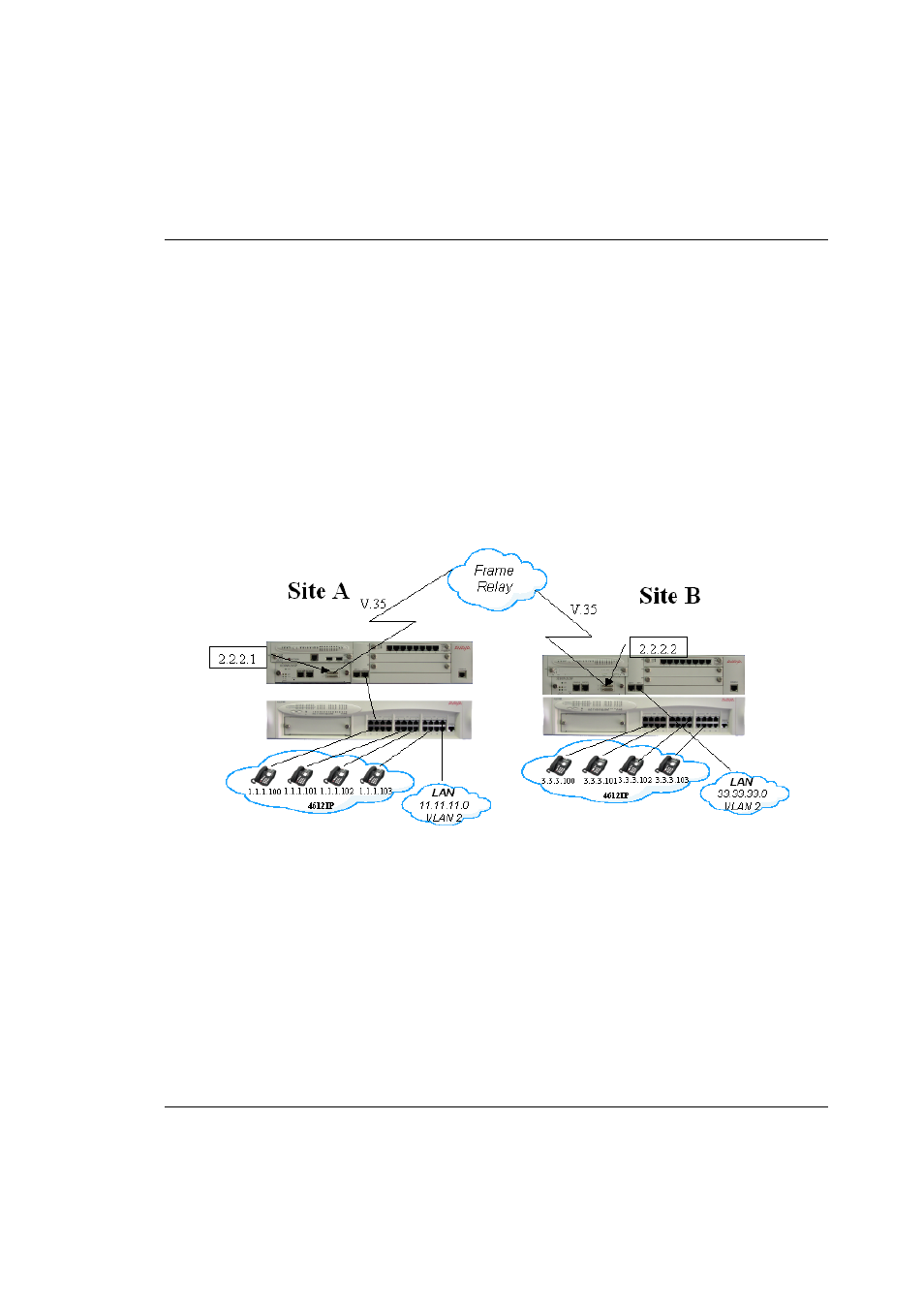
Frame Relay VoIP Configuration
Figure 4.11 illustrates a common Frame Relay VoIP configuration between two sites
connected over a WAN. The following configuration scenarios are provided below
that relate to this illustration:
•
Traffic Shaping - A single VC between Site A and Site B.
•
Priority DLCI and Traffic Shaping - Two VCs between Site A and Site B.
Figure 4.11
VoIP Configuration with Frame Relay Encapsulation
Scenario 1 - Traffic Shaping
In Figure 4.11, Site A contains four IP phones and a data LAN connected via a
P333T-PWR switch to a S8300 Media Server. The S8300 Media Server houses an
X330W-2USP expansion module that is connected to a Frame Relay network via a
192Kbps Frame Relay encapsulated V.35 interface. Following are the connection
details for Site A:
•
A single VC with:
— CIR = 128Kbps:
— DLCI = 16