Console pin assignments, Table a.3, Pinout for console communications – Avaya X330WAN User Manual
Page 248
Appendix A
Interface Specifications
226
Avaya X330WAN User’s Guide
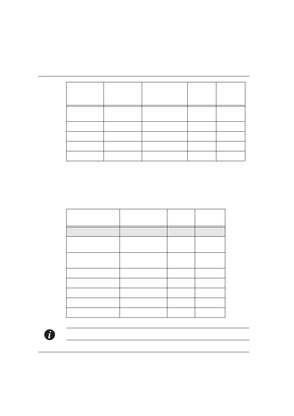
Console Pin Assignments
Table A.3 shows the pinout from the X330WAN RJ-45 connector to both a DB-9 and
DB-25 connector.
Note:
Pin 1 of the Modem DB-25 connector is internally connected to Pin 7 GND.
P1-21
P1-24
MODE<2>
DCE/DTEn
Local connections
---
---
P1-26
GND
Twisted pair #1
---
8
Not used
Twisted pair #4
Not used
Not used
Twisted pair #6
Not used
Not used
Twisted pair #9
Not used
Table A.3
Pinout for Console Communications
X330WAN RJ-45 Pin
Name
Terminal
DB-9 Pin
Modem
DB-25 Pin
1
For future use
NC
See note
2
TXD
(P330 input)
3
3
3
RXD
(P330 output)
2
2
4
CD
4
8
5
GND
5
7
6
DTR
1
20
7
RTS
8
4
8
CTS
7
5
Serial
connector pin
Signal name
Note
Direction
DB-15
connector
pin