Hsv100 controller cabling, 54 hsv100 controller connectors—rear view – HP 3000 Enterprise Virtual Array User Manual
Page 127
Storage System Hardware Components
127
Enterprise Virtual Array 3000 User Guide
HSV100 Controller Cabling
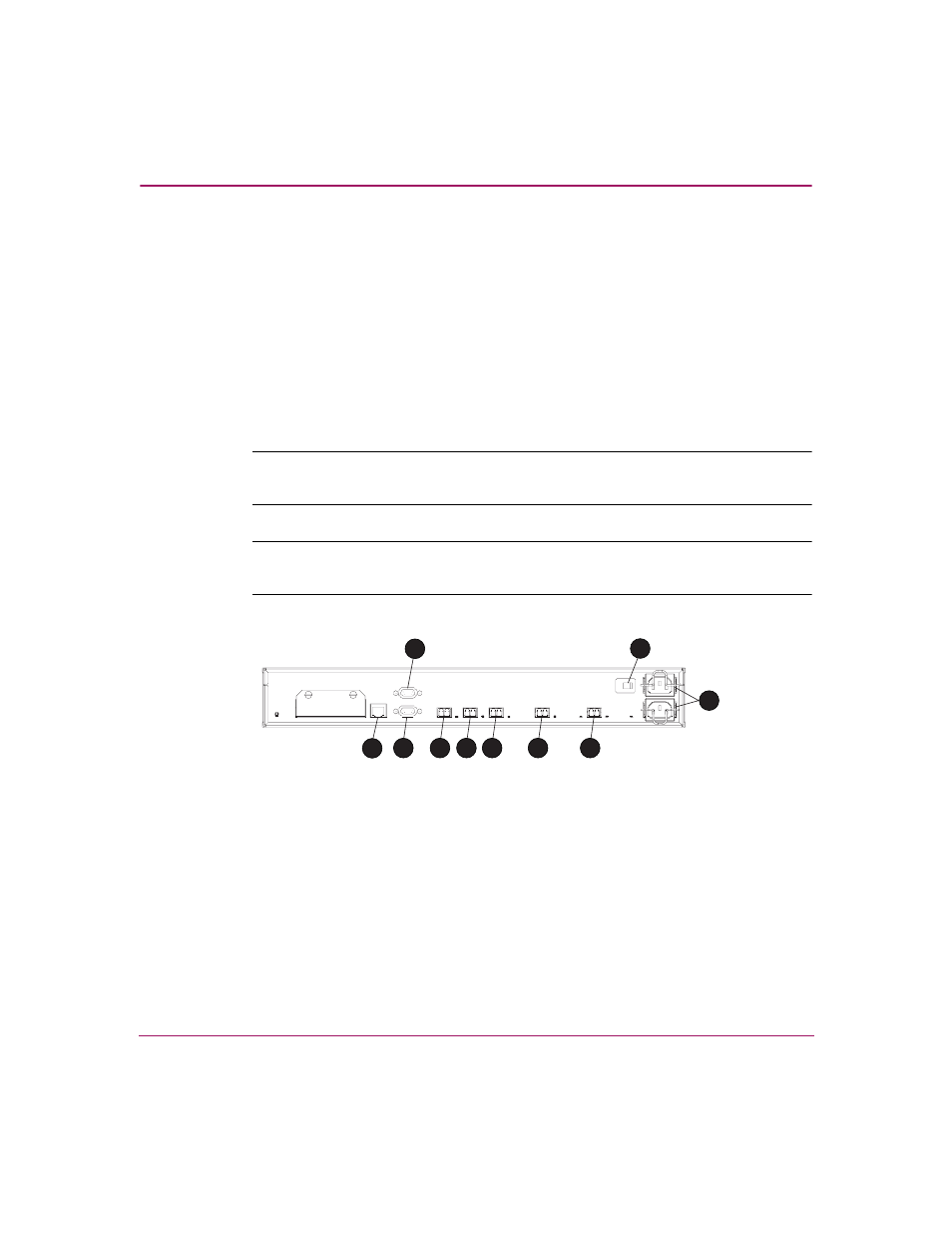
On the rear of the controller are the data and power connections. The data
connections are the interface to the disk drive enclosures, the other controller, and
the fabric (host) or Command View EVA.
All data cables and power cables attach to the rear of the HSV controller. See
. Adjacent to each data connector (see 4, 5, 6, 7, 8, 9, and -) is a
two-colored LED that defines the link status.
■
When the green LED is On, the link can communicate.
■
When the amber LED is On, the link cannot communicate.
Note:
These LEDs do not indicate whether there is communication on the link, only
whether the link can transmit and receive data.
Note:
The connectors are identified by the label printed on the controller. The
information in the parentheses defines the connector function.
1
CAB (enclosure address bus)
2
UART (not used)
3
UART (not used)
4
FP 1 (fabric port 1)
5
FP 2 (fabric port 2)
6
MP (mirror port)
7
1B (loop 1B)
8
1A (loop 1A)
9
AC power switch
-
AC power connectors
Figure 54: HSV100 controller connectors—rear view
CXO8163A
1
2
3
4
5
6
7
8
9
10