HP EVA P6000 Storage User Manual
Page 23
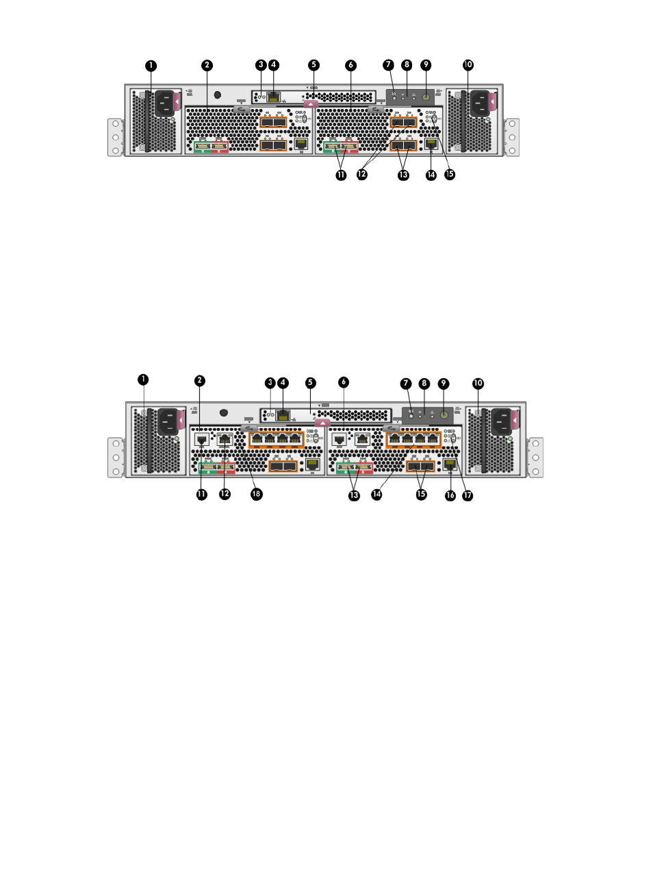
Figure 3 P6000 EVA FC controller enclosure (rear view)
9. Enclosure power push button
1. Power supply 1
10. Power supply 2
2. Controller 1
11. DP-A and DP-B, connection to back end (storage)
3. Management module status LEDs
12. FP1 and FP2, connection to front end (host or SAN)
4. Ethernet port
13. FP3 and FP4, connection to front end (host or SAN)
5. Management module
14. Manufacturing diagnostic port
6. Controller 2
15. Controller status and fault LEDs
7. Rear UID push button
8. Enclosure status LEDs
Figure 4 P6000 EVA FC-iSCSI controller enclosure (rear view)
10. Power supply 2
1. Power supply 1
11. Serial port
2. Controller 1
12. SW Management port
3. Management module status LEDs
13. DP-A and DP-B, connection to back-end (storage)
4. Ethernet port
14. 1GbE ports 1–4
5. Management module
15. FP3 and FP4, connection to front end (host or SAN)
6. Controller 2
16. Manufacturing diagnostic port
7. Rear UID push button
17. Controller status and fault LEDs
8. Enclosure status LEDs
18. iSCSI module recessed maintenance button
9. Enclosure power push button
Controller enclosure
23
- StorageWorks MSL6000 Tape Library (61 pages)
- Лент-е накопители HP StoreEver DAT (64 pages)
- Лент-е накопители HP StoreEver DAT (50 pages)
- StoreEver Ultrium Tape Drives (78 pages)
- StoreEver Ultrium Tape Drives (76 pages)
- Linear Tape File System Software (20 pages)
- StoreEver Ultrium Tape Drives (61 pages)
- StoreEver TapeAssure Software (40 pages)
- StoreEver Ultrium Tape Drives (75 pages)
- StoreEver Ultrium Tape Drives (60 pages)
- Linear Tape File System Software (28 pages)
- Linear Tape File System Software (25 pages)
- 2600fx Optical Disk Drive (65 pages)
- Ленточный автозагрузчик HP StorageWorks DAT 72x10 (58 pages)
- StorageWorks 1000 Modular Smart Array (81 pages)
- StorageWorks 1500cs Modular Smart Array (48 pages)
- StorageWorks 1500cs Modular Smart Array (52 pages)
- StorageWorks 1500cs Modular Smart Array (71 pages)
- 2000fc Modular Smart Array (150 pages)
- StorageWorks 1000 Modular Smart Array (72 pages)
- Servidor de almacenamiento HP ProLiant DL585 G2 (152 pages)
- Sistemas de almacenamiento de red HP StorageWorks X3000 (152 pages)
- Software de HP StoreVirtual VSA (127 pages)
- Software de HP StoreVirtual VSA (85 pages)
- X500 Data Vault (331 pages)
- StorageWorks 1000i Virtual Library System (122 pages)
- StorageWorks XP Remote Web Console Software (20 pages)
- 200 Storage Virtualization System (176 pages)
- XP Array Manager Software (101 pages)
- StorageWorks MSA 2.8 SAN Switch (22 pages)
- StorageWorks MSA 2.8 SAN Switch (104 pages)
- StorageWorks MSA 2.8 SAN Switch (270 pages)
- StorageWorks MSA 2.8 SAN Switch (307 pages)
- StorageWorks All-in-One SB600c Storage Blade (60 pages)
- StorageWorks All-in-One SB600c Storage Blade (72 pages)
- StorageWorks All-in-One SB600c Storage Blade (80 pages)
- StorageWorks All-in-One SB600c Storage Blade (78 pages)
- ProLiant DL585 G2 Storage-Server (150 pages)
- Data Protector Express Basic-Software (83 pages)
- Data Protector Express Basic-Software (93 pages)
- ProLiant DL185 G5 Storage Server (174 pages)
- ProLiant High Availability Storage Server (72 pages)
- StorageWorks 2000fc G2 Modular Smart Array (76 pages)
- 2000I G2-Modular-Smart-Array (48 pages)
- P2000 G3 MSA Array Systems (58 pages)