4 cable connections, Core i/o connections, Revision a gsp – HP 9000 rp5400 Servers User Manual
Page 45
4 Cable Connections
Core I/O Connections
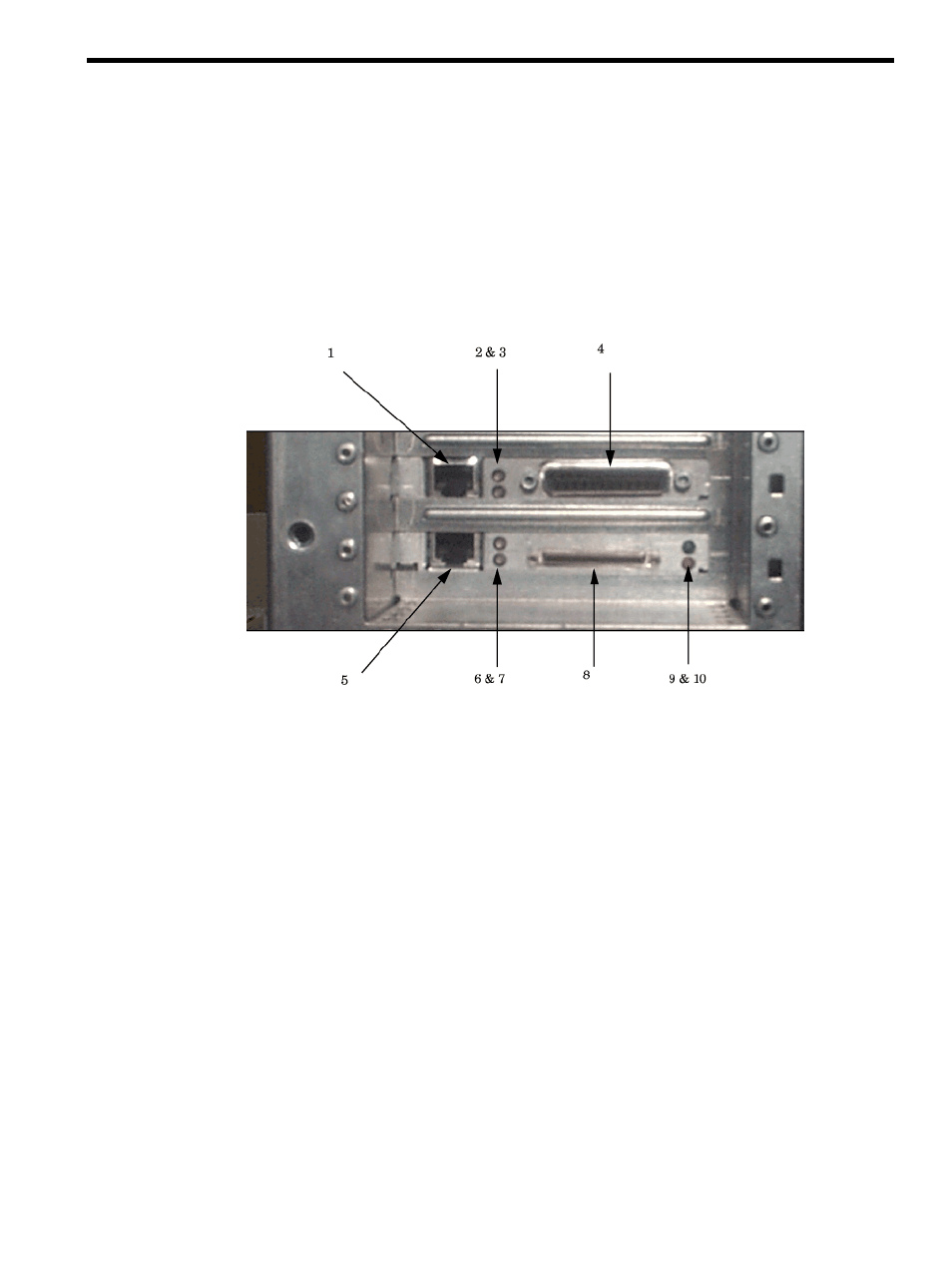
The following paragraphs describe the indicators and connections of the rp54xx Core I/O. Core
I/O consists of a LAN/SCSI card in slot 1 (lower slot in graphic) and a Guardian Service Processor
(GSP) in slot 2 (upper slot in graphic). There are two versions of GSP, revision A and revision B.
Revision A GSP
The following graphic shows the indicators and connectors for the revision A GSP and LAN/SCSI
Core I/O boards.
1.
10-Base-T LAN (RJ-45) Connector
GSP LAN.
2.
Green/Red (Upper LED)
Green = GSP Power On.
Flashing Green = LAN Receive.
Red = Guardian Support Processor Test Failed.
3.
Green/Red, (Lower LED)
Green = Link OK.
Flashing Green = LAN Transmit.
Red = Guardian Support Processor Test Failed.
4.
Console/UPS/Remote Connector (D-Type 25-Pin female).
Requires an A5191-63001 "W" adapter cable
5.
10/100 Base-T = Primary LAN (RJ-45) Connection
Path 0/0/0/0
6.
Green/Yellow (Upper LED)
Green = 100 Base-T Mode
Green Blinking = 100 Base-T Receiving
Core I/O Connections
45
- xt1500 (58 pages)
- LaserJet 4700 (68 pages)
- ProLiant BL460c Gen8 Server Blade (67 pages)
- ProLiant DL360 Server (16 pages)
- ProLiant BL460c Gen8 Server Blade (65 pages)
- ProLiant DL388p Gen8 Server (128 pages)
- ProLiant DL388p Gen8 Server (47 pages)
- ProLiant BL40p Server series (73 pages)
- ProLiant BL465c Server Blade (87 pages)
- ProLiant ML115 Server (63 pages)
- ProLiant DL140 G2 Server (81 pages)
- Servidor HP ProLiant ML370 G4 (30 pages)
- Servidor HP ProLiant ML370 G4 (20 pages)
- Servidor HP ProLiant DL160 G5p (84 pages)
- Servidor HP ProLiant DL980 G7 (143 pages)
- Servidor HP ProLiant DL380 G5 (137 pages)
- Integrity rx2620 Servers (100 pages)
- Integrity rx2620 Servers (37 pages)
- Integrity Superdome sx1000 Server (53 pages)
- Integrity rx2620 Servers (37 pages)
- Integrity rx2620 Servers (58 pages)
- Integrity rx2620 Servers (77 pages)
- Integrity rx2620 Servers (107 pages)
- Integrity rx2620 Servers (55 pages)
- 9000 rp3440 Servers (36 pages)
- Integrity rx2620 Servers (42 pages)
- Integrity rx2620 Servers (48 pages)
- Integrity rx2620 Servers (53 pages)
- Integrity rx2620 Servers (24 pages)
- Integrity rx2620 Servers (33 pages)
- Servidor HP ProLiant DL360p Gen8 (129 pages)
- Servidor HP ProLiant DL120 G6 (133 pages)
- ProLiant DL580 Gen8 Server (91 pages)
- ProLiant MicroServer Gen8 (95 pages)
- ProLiant MicroServer (94 pages)
- ProLiant BL685c G5 Server Blade (99 pages)
- ProLiant Firmware Maintenance CD (87 pages)
- ProLiant BL10e Server Blade (232 pages)
- ProLiant BL40p Server series (30 pages)
- Serveur lame HP ProLiant BL680c G5 (90 pages)
- Serveur lame HP ProLiant BL465c Gen8 (578 pages)
- ProLiant DL320e Gen8 Server (96 pages)
- ProLiant ML110 G7 Server (113 pages)
- 9000 rp8420 Servers (38 pages)
- Integrity Superdome sx1000 Server (19 pages)