Rp5400/rp5450 pci card slots – HP 9000 rp5400 Servers User Manual
Page 32
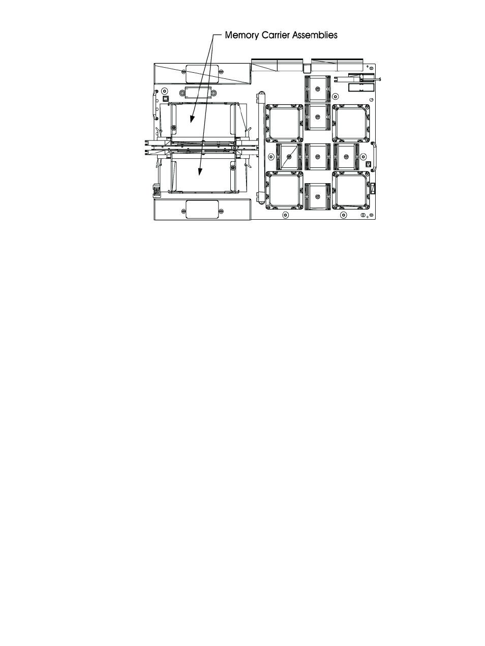
a.
Locate the Memory Carrier and pull up on the extractor levers on each end of the
Memory Carrier to unseat the Memory Carrier from its socket.
b.
When the Memory Carrier unseats from the socket, pull it away from the System Board.
c.
Loosen the captive screws that secure the DIMM Clip and remove the DIMM Clip from
the Memory Carrier.
d.
Seat the memory DIMM into its socket on the Memory Carrier.
e.
Press the extractor levers on each end of the memory DIMM slot inward until the levers
snap into place.
f.
Attach the Memory Clip to the Memory Carrier with the DIMM slot markings on the
top of the Memory Clip aligned with the DIMM slot markings on the Memory Carrier.
g.
Secure the Memory Clip using the captive screws.
h.
Seat the Memory Carrier into the appropriate slot on the System Board.
i.
Push down on the extractor levers and snap them into place.
7.
Replace the air baffle. Tighten the four captive screws to secure the air baffle in place.
8.
Replace the top cover. Slide the cover tabs into the slots in the chassis and close the cover.
Tighten the two captive screws to secure the top cover in place.
9.
For rack configurations, insert the rp54xx server back into the rack.
10. For deskside enclosure configurations, replace the deskside enclosure cover.
11. Power the rp54xx server on.
12. Use the BCH command in meto verify the system recognizes the memory that you have
just added.
Installing Peripheral Component Interconnect (PCI) Cards
rp54xx servers have a total of 12 PCI I/O slots. Slots 1 and 2 are reserved for the LAN/SCSI and
GSP Core I/O cards, leaving 10 PCI I/O slots available for Customer use.
rp5400/rp5450 PCI Card Slots
For rp5400 and rp5450 models, 10 PCI I/O slots consist of Turbo and non-Turbo slots. Server PCI
slots are shown below.
32
Installing Additional Components