Installing rp5470 dimms – HP 9000 rp5400 Servers User Manual
Page 31
8.
Replace the top cover. Tighten the four captive screws to secure the top cover in place.
9.
For rack configurations, insert the rp54xx server back into the rack.
10. For deskside enclosure configurations, replace the deskside enclosure cover.
11. Power the rp54xx server on.
12. Use the BCH command in meto verify the system recognizes the memory that you have
just added.
Installing rp5470 DIMMs
DIMMs for the rp5470 system are installed in memory carriers instead of the system board, as
are the other rp54xx systems. However, rp5470 memory carriers are also located on the system
board, so the method for opening and closing the system is the same. Procedures for removing
and replacing the server top and baffle are listed below, without the pictures shown in the section
titled, "Installing rp5400 and/or rp5450 DIMMs." If you wish to reveiw the pictures, please refer
to the aforementioned section.
1.
Power down and unplug the rp54xx server.
NOTE:
DC voltages are present when the server is connected to AC power. Do not attempt
to install or service: CPUs, Memory, PSMs, the Platform Monitor or PCI I/O cards installed
in non-Turbo slots (1-6) while DC voltage is present. Failure to observe this warning may
result in damage to the server.
2.
Make the top of the server accessible for service.
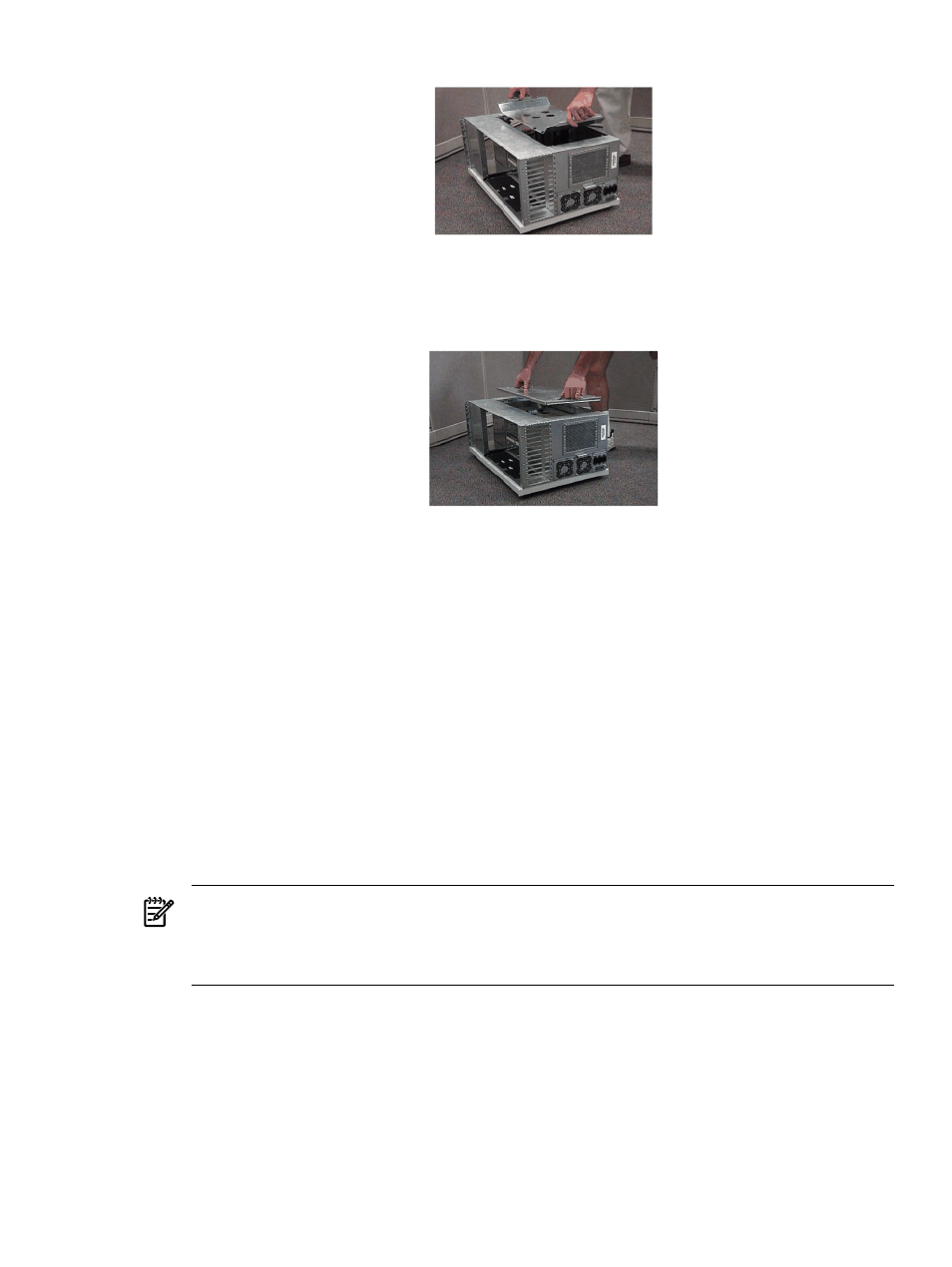
3.
Loosen the captive T-15 screws that hold the top cover in place, then grasp the strap handle,
raise the cover slightly, and pull the cover toward the front of the server to free the cover
tabs from the slots in the chassis. The air baffle will be exposed.
4.
Loosen the four (4) captive T-15 screws on the air baffle. Grasp the two handles on the baffle,
and lift and remove the baffle.
5.
Observe Electrostatic Discharge (ESD) precautions.
6.
Refer to the following graphic for Memory Carrier locations.
Installing Memory
31