Installation – KROHNE OPTIFLEX 2200 C_F EN User Manual
Page 24
3
INSTALLATION
24
OPTIFLEX 2200 C/F
www.krohne.com
07/2013 - 4000668002 - HB OPTIFLEX 2200 R02 en
• Weld a tube with an internal diameter of 12 mm / 0.5¨ to the bottom of the tank.
i
Make sure the tube aligns with the process connection at the top of the tank.
• Lower the probe into the tank.
• Put the end of the probe into the tube.
The probe counterweight has a hole with an M8 internal thread. The other probe end options are
given in the illustration.
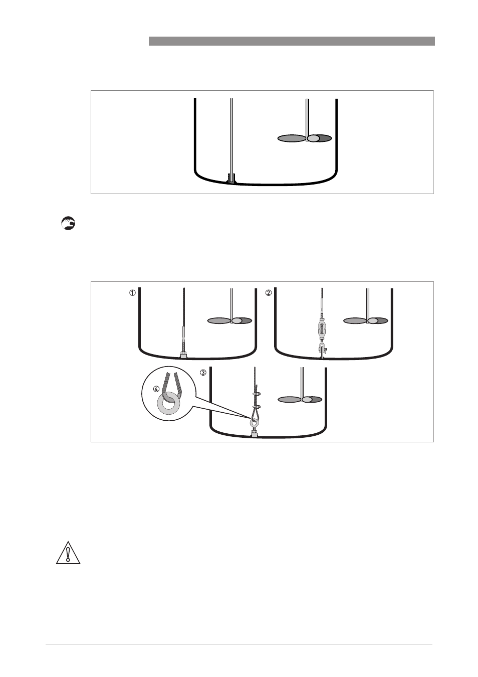
Single rod Ø8 mm / 0.3¨
Figure 3-14: How to attach a single rod probe to keep it straight
Single cable Ø4 mm / 0.15¨
Figure 3-15: How to attach a Ø4 mm / 0.15¨ single cable probe to keep it straight
1 Probe with threaded end
2 Probe with turnbuckle
3 Probe with chuck
4 If you chose a chuck to anchor the probe, we recommend that you fit a ferrule (metal sheath - not supplied) at the
bottom of the loop to prevent cable wear
CAUTION!
If your device has a chuck, you must recalculate the probe length. For the procedure, refer to
How to decrease the length of probes on page 89
. If the device is not set to the correct probe
length, it is possible that the device will not measure correctly.