Service – KROHNE OPTIFLEX 2200 C_F EN User Manual
Page 110
7
SERVICE
110
OPTIFLEX 2200 C/F
www.krohne.com
07/2013 - 4000668002 - HB OPTIFLEX 2200 R02 en
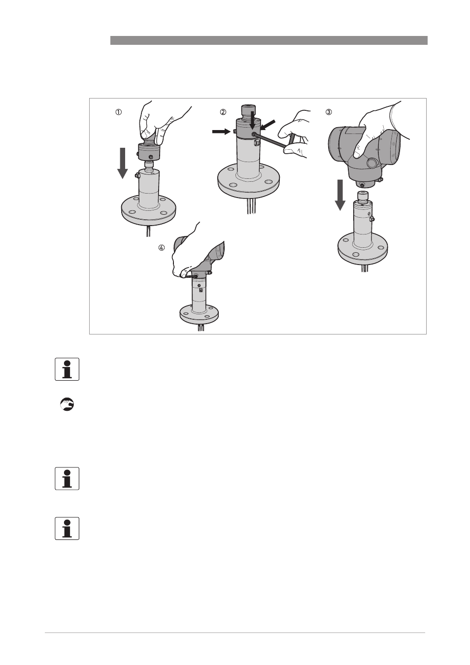
1 Put the adaptor on the process connection. Make sure that the adaptor fully engages in the
mating part.
2 Attach and tighten the socket head screw with a 5 mm Allen wrench.
3 Put the OPTIFLEX 2200 signal converter on the adaptor. Make sure that the signal converter
fully engages in the mating part (adaptor).
4 Tighten the socket set screw at the bottom of the signal converter with a 5 mm Allen wrench.
Procedure 3: How to attach the OPTIFLEX 2200 signal converter
Figure 7-8: Procedure 3: How to attach the OPTIFLEX 2200 signal converter
INFORMATION!
If the OPTIFLEX 1300 was made after 2009, do not do steps 1 thru 2.
INFORMATION!
The adaptor is available as a spare part. Send an order for this part only or for the
OPTIFLEX 2200 signal converter with the adaptor attached. For the order code, refer to Order
code on page 149
.
INFORMATION!
The procedure that follows calibrates the new device. You must have 2 reference points (levels)
in the tank given by a different measurement solution (an approved level meter or indicator).
These points are identified as reference point 1 (R1) and reference point 2 (R2). R1 is the point
where the tank is approximately 20% full. R2 is the point where the tank is approximately 80%
full.